SLAA517F May 2012 – August 2021 MSP430F6720A , MSP430F6720A , MSP430F6721A , MSP430F6721A , MSP430F6723A , MSP430F6723A , MSP430F6724A , MSP430F6724A , MSP430F6725A , MSP430F6725A , MSP430F6726A , MSP430F6726A , MSP430F6730A , MSP430F6730A , MSP430F6731A , MSP430F6731A , MSP430F6733A , MSP430F6733A , MSP430F6734A , MSP430F6734A , MSP430F6735A , MSP430F6735A , MSP430F6736 , MSP430F6736 , MSP430F6736A , MSP430F6736A
6.2.1 Gain Correction
Gain correction for voltage, current and active power can be done simultaneously and the procedure is discussed below.
- Connect the meter to the test setup with known voltage and currents.
- Connect GUI to view results for voltage, current, active power, and so forth.
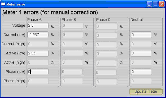
- Click on Manual cal seen in Figure 6-2 to give you this screen.
 Figure 6-4 Meter 1 Errors (for manual correction)
 - The values that need to be entered are in % and these values are calculated by the formula in Equation 7. For any particular voltage, the value will be:
Equation 7.

- Negative values are accepted in the voltage and current fields and the same procedure is applicable for other voltages and currents. For voltages, enter in field "Voltage" and for currents, enter in field Current (low). After these values are entered, click on Update meter.
- Gain correction for active power is done differently; the accuracy obtained from any test system when pulses are fed from the meter is the most accurate method.
- Measure accuracy in the reference meter of the test system. This gives the true accuracy of the meter for active energy.
- Enter the "% accuracy" seen as-is in the Active (low) field. Click on update meter to do a gain correction on Phase A.