SLAA517F May 2012 – August 2021 MSP430F6720A , MSP430F6720A , MSP430F6721A , MSP430F6721A , MSP430F6723A , MSP430F6723A , MSP430F6724A , MSP430F6724A , MSP430F6725A , MSP430F6725A , MSP430F6726A , MSP430F6726A , MSP430F6730A , MSP430F6730A , MSP430F6731A , MSP430F6731A , MSP430F6733A , MSP430F6733A , MSP430F6734A , MSP430F6734A , MSP430F6735A , MSP430F6735A , MSP430F6736 , MSP430F6736 , MSP430F6736A , MSP430F6736A
3.1.1 Resistor Capacitor (RC) Power Supply
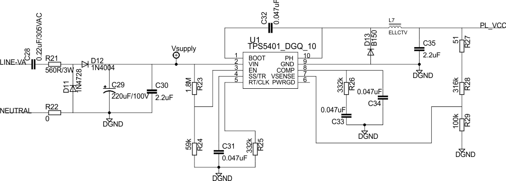
Figure 3-1 shows a simple capacitor power supply for a single output voltage of 3.3 V directly from the mains voltage of 110 V and 220 V and 50 Hz and 60 Hz VRMS ac.
 Figure 3-1 A Simple Capacitive Power Supply for the MSP430 Energy Meter
Appropriate values of resistor R21 and capacitor C28 are chosen based on the required output current drive of the power supply. Voltage from mains is directly fed to a RC-based circuit followed by rectification circuitry to provide a dc voltage for the operation of the MSP430 MCU. This dc voltage is regulated to 3.3 V for full-speed operation of the MSP430 MCU. For the circuit in Figure 3-1, the drive provides approximately 12 mA. The design equations for the power supply are given in the Improved Load Current Capability for Cap-Drop Off-Line Power Supply for E-Meter application report. If there is a need to slightly increase the current drive (up to 20 mA), the capacitor values of C28 can be increased. If drive higher than 20 mA is required, especially to drive RF technology, additional drive can be used either with an NPN output buffer or a transformer and switching-based power supply.