SLAA732A February 2017 – April 2021 PGA460 , PGA460-Q1
3.1 Range Requirements
Firstly, consider the minimum and maximum range requirements. A common range requirement for air-coupled ultrasonic transducer measurements is, but not limited to, object detection between 30 cm to 8 m. Short-range measurements are a challenge for single-transducer configurations, whereby the transducer acts as both the transmitting and receiving element. Because of the resonant behavior of transducers, residual energy will oscillate within the transducer for a short duration immediately after excitation. This short post-burst duration is referred to as the ringing or decay time. The decay time is based on the equivalent model of the transducer, how long and strongly the transducer is excited, the matched or unmatched resonance frequency of the driver components (based on secondary leakage inductance of the transformer), and resonant frequency offset from the center-frequency of the band-pass filter.
Section 4.4 presents the techniques on external matching network-compensation design for improved short-range performance. The matching network consists of inductive, capacitive, and resistive components, which can be optimized to reduce decay time and improve the minimum distance that can be measured using an ultrasonic sensor. Long-range measurements are less of a concern because the decay profile has typically subsided to the same level as the noise floor at the time of object detection. When using a dual-transducer (bi-static) configuration, which includes a separate transducer dedicated exclusively to transmitting, and another transducer dedicated to receiving, the decay time becomes irrelevant because the receiving transducer is only excited by the returning ultrasonic echo. Dual-transducer configurations are recommended for very short object detection (at nearly 0 cm).
Long-range detection must account for the attenuation of ultrasonic energy as it attenuates through air. The rate of attenuation is primarily dependent on frequency. The relationship of transducer frequency to maximum detectable distance is provided as the following:
↑ Frequency :: ↑ Resolution :: ↑ Narrower Directivity :: ↑ Attenuation :: ↓ Distance
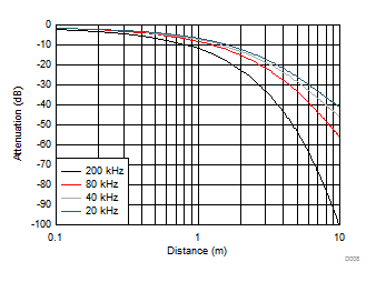
Ultrasonic energy does not decay linearly across distance. Figure 3-1 shows the attenuation of sound pressure by distance and frequency.
 Figure 3-1 Attenuation Characteristics of Sound Pressure by Distance
The benefits of high-frequency transducers include an increase to resolution and focused directivity (forward facing beam pattern), but the disadvantage is the increase to attenuation. The rate at which the ultrasonic energy experiences scattering and absorption while propagating through the medium of air increases with frequency and therefore the decrease in maximum detectable distance.