SLAA941 March 2020 TUSS4440 , TUSS4470
2.1 MCU Initialization
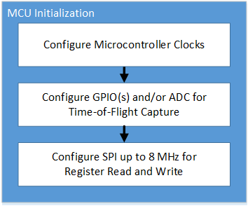
The internal clocks, SPI ports, GPIOs, and ADC of the master controller must be configured prior to initialization of the TUSS44x0 registers.
 Figure 3. MCU Initialization
 The SPI terminal of the master controller must be configured to meet the TUSS44x0 requirements for SDI, SDO, SCLK, and NCS pins. The SPI supports up to an 8 MHz clock, and is formatted in a 16 data bit frame with MSB first. The master SPI should match SPI MODE 1 (CPOL = 0 and CPHA = 1), such that the SDO is sampled on the falling edge of the SCLK pin, and the SDI is shifted out on the rising edge of the SCLK pin. The SPI logic level of the TUSS44x0 device is equal to the value of VVDD that can be set to a value between 3.1 V and 5.5 V. This means traditional 3.3 V or 5.0 V logic level MCUs can interface with the TUSS44x0. Because the logic level is typically limited to a single voltage, and fixed for most systems, the default logic level is referenced to 3.3 V for compatibility with the MSP430F5529 microcontroller.
Depending on the I/O driver mode used by the TUSS44x0, either one or two MCU GPIOs must be configured as outputs to drive the IO1 and IO2 pins. When using IO_MODE1 or IO_MODE2, two GPIOs must be configured as outputs for both IO1 and IO2 pins. When using IO_MODE0 or IO_MODE3, only one GPIO must be configured as an output for pin IO2; pin IO1 is not used in these cases.
Depending on the type of data response from the TUSS44x0 that the MCU is to capture, one or two GPIOs must be configured as inputs, or one ADC input capture is to be enabled.