SLAU892 March 2023 AFE11612-SEP
3.2.2.1.2 ADCs Subpage
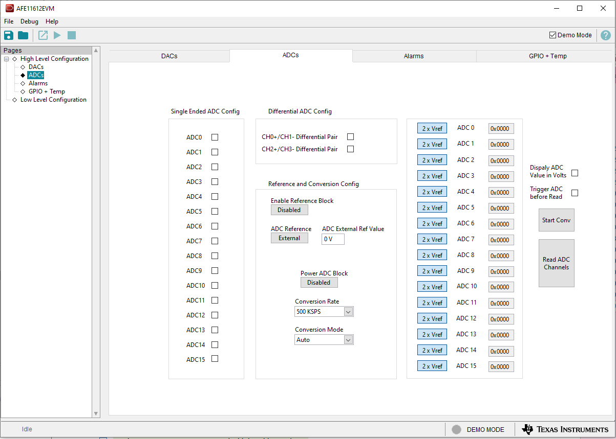
Figure 3-6 shows the ADCs subpage. This page provides insight into the functionality of the AFE11612-SEP, a 16-channel, 12-bit ADC. The ADC block can be configured as 16 single-ended inputs (ADC0 to ADC15) or as 2 differential inputs (ADC0 to ADC3) plus 12 single-ended (ADC4 to ADC15). With VREF defined as the reference voltage input to the ADC, the analog input range for the device can be selected as 0 V to VREF (2.5 V) or 0 V to 2 × VREF (5 V).
 Figure 3-6 ADCs Subpage
Most of the controls listed within the ADC subpage are used to set up the ADC configuration register. These controls include the conversion-rate and conversion-mode parameters, which are selectable through the respective drop-down menu. The conversion mode can be either Auto or Direct. In Direct mode, the analog inputs specified in the ADC channel registers are converted sequentially one time. In Auto mode, the analog inputs are converted sequentially and repeatedly. After a conversion is completed, the ADC multiplexer returns to the first channel and repeats the process.
The ADCs also have the option to use an external or internal reference. To enable the external reference, press the External button located under ADC Reference. If the button is not selected, the internal reference is enabled. When the external reference is selected, the ADC External Ref Value field is used to enter a value. This value is used to calculate the ADC conversion in volts when the Display ADC Value in Volts checkbox is selected.