SLDU007C March 2012 – November 2015 PGA450-Q1
-
PGA450Q1EVM User’s Guide
- Trademarks
- 1 Read This First
- 2 EVM Overview
- 3 Power-Supply Requirements and Connections
- 4 Jumper Settings
- 5 Socket for Programming OTP
- 6 Transformer and Transducer
- 7 PGA450-Q1 Communication Interfaces
- 8 Controlling the PGA450-Q1 Memory Spaces With the GUI
- 9 LIN Master
- 10 Keil uVision Settings for Programming Firmware to the PGA450-Q1 DEVRAM or OTP Memory
- 11 Use Case
- 12 PGA450Q1EVM Schematics and Layout Drawings
- Revision History
6 Transformer and Transducer
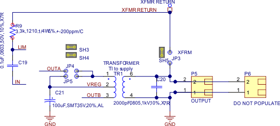
A matched transformer-transducer pair is included on the PGA450Q1EVM.

A matched transformer-transducer pair is included on the PGA450Q1EVM. Table 4 lists closed-top transducers and tunable push-pull transformers from various manufacturer numbers that can be matched with a tuning capacitor to create a sensor pair. By default, the transducer and transformer provided with the EVM are the Murata MA58MF14-7N and Mitsumi K5-R4, respectively.
Table 4. Transducer and Transformer Manufacturer Part Numbers
| Manufacturer | Part Number |
|---|---|
| Transducer (at P5 or P6) | |
| Murata | MA58MF14-7N |
| Murata | MA58AF14-0N |
| Transformer (TR1) | |
| Mitsumi | K5-R4 |
| Toko | N1342DEA-0008BQE=P3 |
Murata has provided the following note with regard to the availability and ability to order their ultrasonic sensors:
- For small quantity sample requests, inquire online at the Murata website: https://www.murata.com/en-us/contactform.
- For consumer-grade applications exposed to controlled environments, consider open-structure sensors, such as the Murata MA40H1S-R. Distributors will typically have these sensors readily available for purchase online.
- For automotive-grade sensors (such as the transducers listed in Table 4 for applications exposed to harsh environments, consider closed-top waterproof sensors, and inquire with distributors. The distributors will then request an order with Murata. Lead times for these sensors may vary up to several weeks.
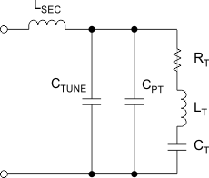
Key ultrasonic sensor specifications are frequency, sensitivity, and directivity. The transformer is used to excite the transducer. The transformer is center tapped to double the voltage. Typically, a tuning capacitor is needed to match the resonant frequency between the transducer and transformer.

CPT, RT, LT, and CT are characteristics of the transducer, LSEC is the secondary inductance of the transformer, and CTUNE is an external capacitor placed across the terminals of the transducer.
 Figure 3. Equivalent Circuit of Transformer-Transducer Sensor Pair