SLLA486A May 2020 – May 2021 ISO1042 , ISO1042-Q1 , ISO1044 , ISO1050 , ISOW1044
- Trademarks
- 1 When Do I Need to Isolate CAN?
- 2 What are the Options Available to Isolate CAN Bus?
- 3 Now That I Have Isolated CAN Signal Path, How Do I Generate Isolated Power?
- 4 What’s the Reason Behind Terminating the Bus, Do I Need it, and How to Achieve it?
- 5 What’s the Difference Between Common Mode Range and Bus Standoff Mentioned in Data Sheet?
- 6 Now That I Have Taken Care of the Termination Resistor, What Other Components do I Need on the Bus Side?
- 7 When Connecting Isolated CAN Nodes in a Network, What Should be Done with the Floating Bus-Side Ground Connection?
- 8 Is There a Limitation on Minimum Data Rate That I Can Operate? What About the Maximum Data Rate Achievable in a Network?
- 9 Is There a Limit on Maximum Number of Nodes That I Can Connect in CAN Network?
- 10What Factors Decide the Maximum Communication Distance in a CAN Network?
- 11What is the Maximum Value of Bus Capacitance That Can be Introduced Between CANH to GND and CANL to GND? Can Higher Capacitance Damage the Device?
- 12Is There a Way to Extend the Maximum Communication Distance?
- 13What is Stub Length? What are the Design Considerations Around it?
- 14I am Seeing Larger Differential CAN Voltage for Some Bits of CAN Packet Compared to Rest of the Packet When I am Communicating in a Network with Multiple Nodes Connected. Why?
- 15References
- 16Revision History
4 What’s the Reason Behind Terminating the Bus, Do I Need it, and How to Achieve it?
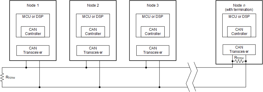
The ISO11898 standard specifies the network interconnect medium to be a single twisted pair cable (shielded or unshielded) with 120-Ω characteristic impedance (ZO). Resistors equal to the characteristic impedance of the line should be used to terminate both ends of the cable to prevent signal reflections. Termination resistors should be placed at the two extreme ends of the network as shown in Figure 4-1. Another reason of CAN bus needing a termination for proper functionality (unlike another industrial interface, RS-485, where termination is optional) is that the dominant-to-recessive signal edge is not actively driven, so the RC decay of the bus brings that transition. If no termination is present on the bus, the dominant-to recessive transition may be missed if the TXD input is continuously changing, resulting in data loss.
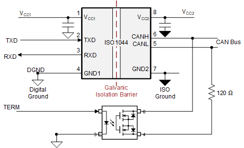
For the networks where new nodes will continually be added, and if there is a requirement to keep hardware design of nodes similar, software-controlled termination is a good design option as shown in Figure 4-2. An OptoMOS (photorelay) circuit can be added to each node design. Through software, the design can enable or disable termination across CANH-CANL by driving TERM through a GPIO of the MCU. So the two farthest end nodes in the network can drive TERM=High to enable termination of 120 ohm across the bus, while all other nodes can drive TERM=Low. This way the CAN bus effective termination is 60 ohm (120 ohm on both ends in parallel); while the hardware design of each node can be the same.
 Figure 4-1 Typical CAN bus Network
 Figure 4-2 Software-Controlled Termination using OptoMOS