SLOU558B August 2022 – January 2023 DRV8452 , DRV8462 , DRV8962
- Abstract
- Trademarks
- 1 Introduction
- 2 Jumpers Table and Setup
- 3 Software Setup
- 4 Hardware Setup
- 5 Launching the DRV84xx_DRV82x2_DRV89x2-EVM GUI Application
- 6 GUI Operations DRV8461EVM, DRV8462EVM, and DRV8462VEVM
- 7 GUI Operations DRV8962EVM and DRV8962VEVM
- 8 GUI Operations DRV8262EVM and DRV8262VEVM
- 9 Updating Firmware
- 10Evaluation Hardware Overview
- A Appendix A
4 Hardware Setup
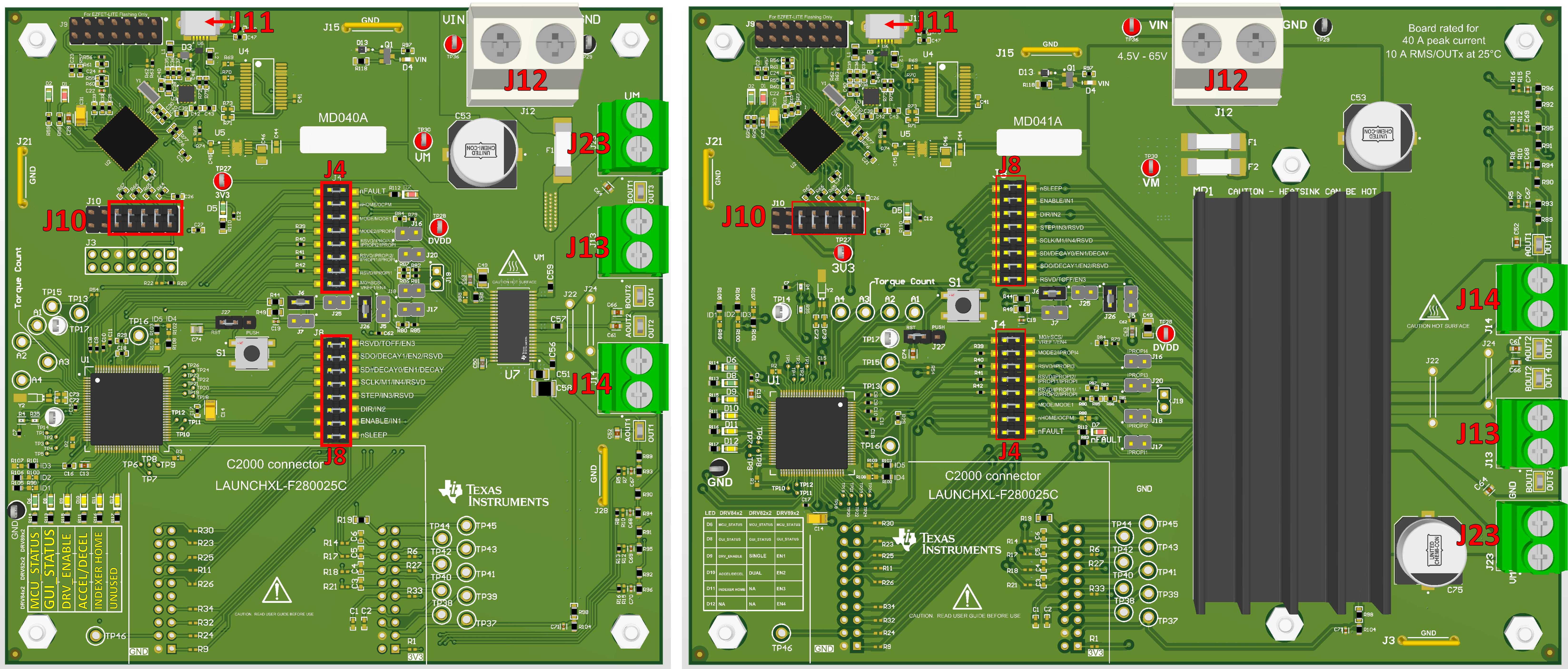
Refer to GUID-2EB5BE4D-9452-4354-8D7E-DD2DC13114B3.html for EVM-specific top view. The figure below shows the connector locations for the DRV8962EVM on the left and the DRV8962VEVM on the right.
- Connect the USB cable to J11 of the EVM and a computer.
- If utilizing the stepper motor driver DRV8452, DRV8461, or DRV8462, connect the stepper motor to screw terminal connectors J13 and J14. A-phase can be connected to J14 and B-phase to J13.
- If utilizing the full bridge driver DRV8252 or DRV8262, brushed DC motor 1 can be connected to J13 and motor 2 can be connected to J14.
- If utilizing a half-bridge driver device DRV8962 or DRV8952 then J13 and J14 will be outputs and J23 will be used for the high side and low side load power supply connections.
 Figure 4-1 Connector Locations on DRV8962EVM (left) and DRV8962VEVM (right).
 Connector | Explanation |
|---|---|
J11 | Micro-USB Connection |
J12 | Fuse protected power supply input and GND |
J23 | Power supply connection high side and low side connection terminals. Only utilized on DRV8962EVM. |
J13 | BOUT1/OUT3, BOUT2/OUT4 connection point. |
J14 | AOUT2/OUT2, AOUT1/OUT1 connection point. |
The EVM connectors and board design are rated beyond the maximum outputs of the motor driver chip installed on it. Specifically for the DRV8x62VEVM, J12 supports 40A peak current, 10A RMS per OUTx connector at 25°C ambient temperature, and J13, J14, and J23 each support 20A RMS.
The MD040E2 revision EVM PCB silk screen has the following errata.
- The Silk screen says OUT3, it should say OUT4
- The Silk screen says OUT4, it should say OUT3
On J4 the Silk screen says RSVD/IPROPI3, it should say RSVD/IPROPI3/IPROPI2/IPROPI
On J4 the Silk screen says RSVD/IPROPI1/IPROPI2/IPROPI, it should say RSVD/IPROPI
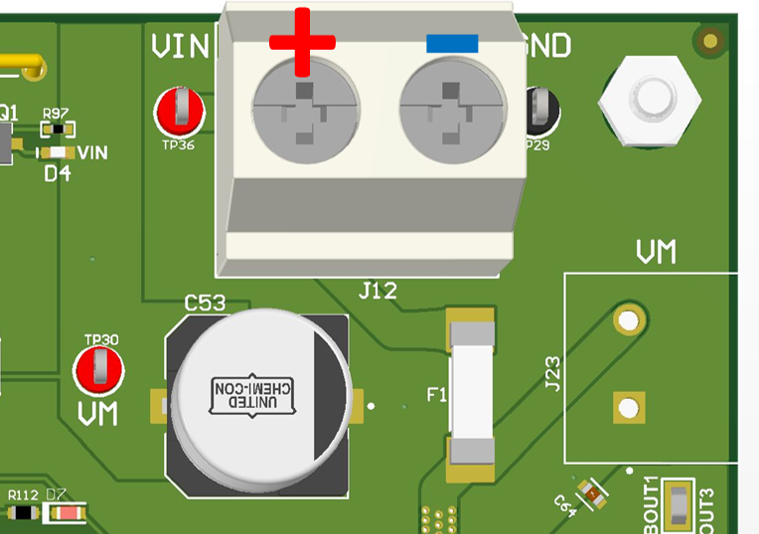
Observing correct polarity connect the VM power supply to the large screw terminal block J12.
CAUTION: A reverse polarity connection can permanently damage the EVM hardware and can cause a fire hazard and / or personal injury.In J12 VM positive is on the left and GND is on the right. VM input is fuse protected
 Figure 4-2 Polarity of J12
- Verify the 3V3 LED D5 and VM LED D4 are illuminated. The nFAULT LED D7 may flash momentarily when VM power is switched on.
- Verify MCU_STATUS LED D6 is blinking at approximately 1 Hz. If the STATUS LED is not blinking perform a firmware reset using the push button S1 with jumper J27 in 1-2 RST position.
- The MCU_STATUS LED D6 will blink now if the EVM hardware is functioning normally
- The EVM is ready to be used with the GUI application (Launching the DRV84xx_DRV82x2_DRV89x2-EVM GUI Application). In certain situations, such as while disconnecting and reconnecting VM power before the power supply capacitors are fully discharged a proper firmware reset can fail to happen. A proper reset is indicated by the STATUS LED D6 blinking at a rate of approximately 1 Hz. If the Status LED is not blinking as expected, press the reset push button once with jumper J27 installed in the RST position.
- Do not unplug the USB cable while the VM power is active. If you do, switch off the VM power, wait until the VM power is fully discharged and proceed to step 2.
- The latest version of the GUI application is bundled with the latest version of the EVM firmware.
- A firmware update is suggested before selecting and connecting to an EVM variant using the GUI application. The firmware update procedure is described in the updating firmware section of this User's Guide.
Preproduction versions of the EVM (MD040E1, MD040E2, MD040E3, and MD041E1) and silicon were used with version 0.1.0 of the GUI. MD040: DRV8461EVM, DRV8462EVM, DRV8962EVM, and DRV8262EVM. MD041: DRV8462VEVM, DRV8962VEVM, and DRV8262VEVM. These versions of EVM should continue to use version 0.1.0 of the GUI. There are address changes in the registers that would result in unexpected behavior using preproduction silicon with 1.0.0 GUI. If you updated the firmware to 1.0.0 GUI, update it again from the 0.1.0 GUI to revert to the original firmware. The Windows installer for 0.1.0 can be downloaded here.
The latest version of the EVM (MD040A and MD041A) should be shipped with the latest firmware, but they could also benefit from performing a firmware update.