SLVAE32B August 2018 – December 2023 TPS7H2201-SP
- 1
- Abstract
- Trademarks
- 1 Device Overview
- 2 Single-Event Effects
- 3 Test Device and Evaluation Board Information
- 4 Depth, Range, and LETEFF Calculation
- 5 Irradiation Facility and Setup
- 6 Test Setup and Procedures
- 7 Single-Event-Latchup (SEL), Single-Event-Burnout (SEB), and Single-Event-Gate-Rupture (SEGR)
- 8 Single Event Transient (SET)
- 9 Total Ionizing Dose From SEE Experiments
- 10Orbital Environment Estimations
- 11Confidence Interval Calculations
- 12Summary
- 13References
- 14Revision History
7.2 Single-Event-Burnout (SEB) and Single-Event-Gate-Rupture (SEGR)
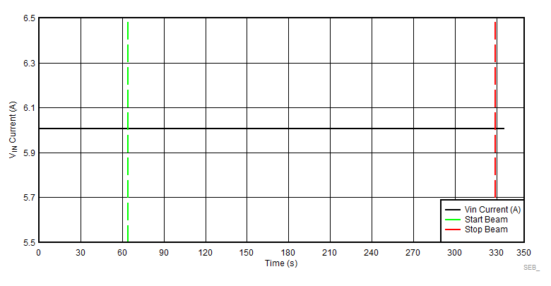
SEB and SEGR were performed at room temperature, with141Pr with an angle of incidence of 0° and 27.3° die for an LETEFF of 66.43 and 75 MeV × cm2 / mg, respectively. The VIN was held at the maximum recommended voltage of 7 V. Flux of approximately 105 ions / cm2 × s and fluence ≥ 2 × 10⁷ ions / cm2 was used in each run. The device was evaluated when the DUT was enabled and disabled, and loaded to 6 A at all times. Even when the device was disabled, the device was loaded (6 A) to help identify if the device was changing modes or closing the switch (disabled to enabled), due to heavy-ions. When the DUT was disabled, the die temperature was at room temp (approximately 23°C), however, when the part was enabled and loaded with six amps, the power dissipated across the pass element increments the die temperature. To test the device around (20°C to 25°C), an external cool element (vortex tube) was used. The stream of cold air was pointed at the die to chill the device during the testing. No change on current was observed, indicating that the TPS7H2201-SP is SEB and SEGR immune at T = 25°C and LET = 75 MeV × cm2 / mg. During the SEB and SEGR testing with the switch disabled the current never increment, indicating that the device never changed status during the exposure. Table 7-2 lists the conditions used for this test. Figure 7-2 shows a typical VIN current versus time plot. The SEB and SEGR cross-section was calculated based on 0 events observed using a 95% (2σ) confidence interval and combining (or summing) fluences (see Section 11 for discussion of confidence limits).
| Run Number | Unit Number | Temperature (°C) | Ion Type | Angle of Incidence (°) | LETEFF (MeV × cm² / mg) | FLUX (ions / cm² × s) | FLUENCE (ions / cm2) | VIN (V) | Load (A) | Enabled? | SEB or SEGR Events |
|---|---|---|---|---|---|---|---|---|---|---|---|
| 3 | 1 | 25 | Pr | 27.3 | 75 | 1.08 × 10⁵ | 2 × 10⁷ | 7 | 6 | Yes | 0 |
| 4 | 2 | 20 | Pr | 27.3 | 75 | 1.28 × 10⁵ | 3 × 10⁷ | 7 | 6 | Yes | 0 |
| 5 | 2 | 20 | Pr | 27.3 | 75 | 1.16 × 10⁵ | 3 × 10⁷ | 7 | 6 | No | 0 |
| 6 | 3 | 25 | Pr | 0 | 66.43 | 1.07 × 10⁵ | 2.01 × 10⁷ | 7 | 6 | Yes | 0 |
| 7 | 3 | 25 | Pr | 0 | 66.43 | 1.03 ×10⁵ | 2 × 10⁷ | 7 | 6 | No | 0 |
 Figure 7-2 Current Versus Time for SEB
and SEGR Run 4 at T = 20°C and 75 MeV × cm2 / mg