SLVAE49C April 2019 – April 2022 DRV8847 , DRV8873-Q1 , DRV8904-Q1 , DRV8906-Q1 , DRV8908-Q1 , DRV8910-Q1 , DRV8912-Q1
2.1.3 Load Connected in H-Bridge
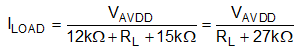
The OLD monitoring when there is a load to the H-bridge will depend on the load resistance (RL). The load's current (IL) for a load connected between OUT1 and OUT2 is calculated as,
This OLD example will trigger an OLD event. The voltages at the positive terminal of OL1_HS (VOL_HS(+)) and the negative terminal of OL2_LS (VOL_HS) will be as follows:
High-side comparator of OUT1's half-bridge (OL1_HS)
If VOL_HS(+) is greater than VOL_HS (2.3 V), the output of OL1_HS is set to "1". The voltage comparison between VOL_HS(+) and VOL_HS required for the output of OL1_HS to be set to "1" is determined as:
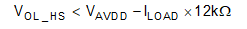
Putting Equation 7 into Equation 8,
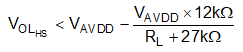
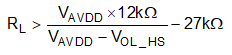
Solving Equation 9 for the load resistance (RL), RL is expressed as,
By using the values of VAVDD and VOL_HS in Equation 10, the load resistance (RL) is calculated as (-)473.7 Ω. Since the value of the resistance is negative, VOL_HS(+) is greater than VOL_HS (2.3 V) and the output of OL1_HS is is set to "1".
Low side comparator of OUT2's half-bridge (OL2_LS)
If the voltage at negative terminal of OL2_LS (VOL_LS(-)) is less than VOL_LS (1.2 V), then the output of OL2_LS is set to "1". Hence, the voltage comparison between VOL_LS(-) and VOL_LS required for the output of OL2_LS to be set to "1" is calculated as:
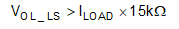
Putting Equation 7 to Equation 11,
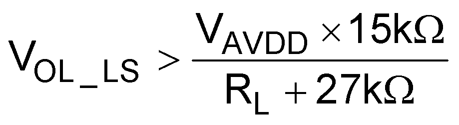
Solving Equation 12 for RL, RL is expressed as,
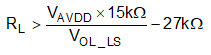
Using the values of VAVDD and VOL_LS in Equation 13, RL has to be greater than 25.5 kΩ for OL2_LS to be set to "1". Since the output of OL1_HS is always set to "1", the OLD status is solely dependent on the output of OL2_LS. If the RL is less than 25.5 kΩ, then an OLD flag will not occur.