SLVAE49C April 2019 – April 2022 DRV8847 , DRV8873-Q1 , DRV8904-Q1 , DRV8906-Q1 , DRV8908-Q1 , DRV8910-Q1 , DRV8912-Q1
2 Passive Open Load Detection
The passive OLD is also referred to as the offline OLD, where the OLD is carried out before the FETs are turned ON. This diagnostics feature ensures that the load is connected to the driver before driving the load. Passive OLD cannot be utilized at the same time as other OLD diagnostics. Load connections to supply, to GND, and in an H-bridge can be detected with passive OLD integrated drivers.
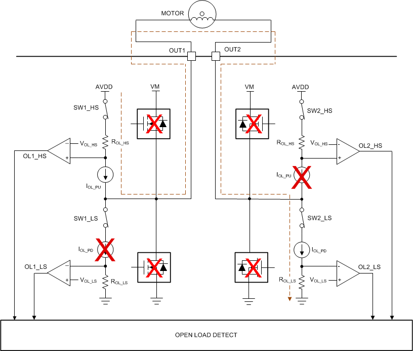
Figure 2-1 shows the circuit implementation of the passive OLD in BDC and stepper motor integrated drivers. For gate drivers, the circuit implementation is similar, with the difference being the FETs are not integrated. The FETs must be in Hi-Z state. Internal source / sink current sources drive current into the load connected between, for example, OUT1/SH1/DL1 and OUT2/SH2/DL2 during a set deglitch time and are limited by the load’s resistance. The diagnostic current is very low (~100 µA for DRV8847) such that it doesn’t rotate the load. If the load is connected between OUT1/SH1/DL1 and OUT2/SH2/DL2, a low-impedance path is created, causing the diagnostics current to be high and operate in saturation. However, if the load is disconnected from the either of OUT1/SH1/DL1 and OUT2/SH2/DL2, a high-impedance path is created, causing the current to be reduced to zero. The voltage at the comparators inputs that share the same node as the current sources fluctuates with the current variation. When the comparator positive terminals are greater than the negative reference voltage terminals, the comparator outputs are high. These comparator outputs are the OLD flags. Passive OLD is not enabled if any other fault other than OCP/OLD are present.
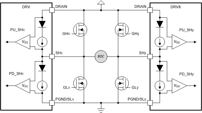
For BDC gate drivers, the motor driver provides the necessary hardware to conduct passive OLD diagnostics of the external FETs and the load. The differences between this passive OLD diagnostic and the passive OLD diagnostic found in integrated and BLDC gate drivers are: BDC gate driver passive OLD recommends the VDS comparator thresholds should be adjusted to 1-V or greater to ensure enough headroom for the internal blocking diode forward voltage drop and the internal OLD pull-up and pull-down circuits replace the OLD resistors with internal blocking diodes, as shown in Figure 2-2.
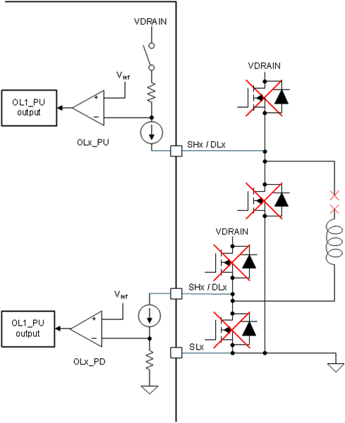
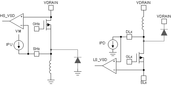
Figure 2-3 shows the circuit implementation of the passive OLD in BLDC gate drivers. The load phase pin to ground capacitances must discharge before passive OLD is enabled. Single phase high-side and low-side loads are not supported in BLDC gate drivers, as shown in Figure 2-4.
In integrated low-side drivers, only low-side OLD current sources are required to detect if a passive OLD event has occurred.
 Figure 2-1 Passive OLD Circuit in an
Integrated Driver
 Figure 2-2 Passive OLD Circuit in a
Brushed DC Gate Driver
 Figure 2-3 Passive OLD Circuit in a
Brushless DC Gate Driver
 Figure 2-4 Passive OLD Load
Configurations not supported in a Brushless DC Gate Driver