SLVAEX0 October 2020 TPS1H000-Q1 , TPS1H100-Q1 , TPS1H200A-Q1 , TPS1HA08-Q1 , TPS1HB16-Q1 , TPS1HB50-Q1 , TPS2HB16-Q1 , TPS2HB50-Q1 , TPS4H000-Q1 , TPS4H160-Q1
3.4 Thermal Shutdown
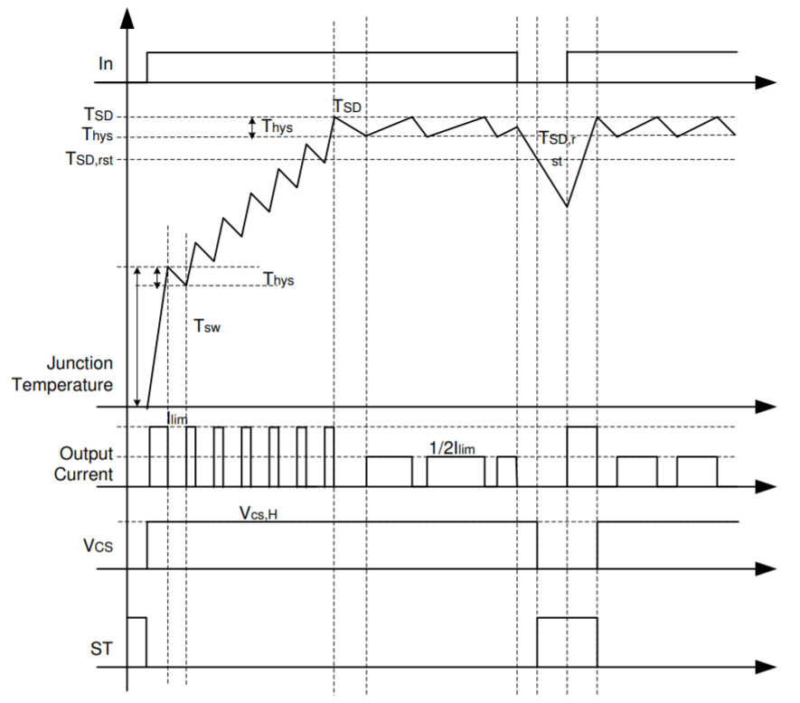
There are two types of faults that detail the smart devices thermal behavior. As the device dissipates power, the device’s junction temperature will increase. The first thermal fault could occur is absolute thermal shutdown and happens when the device’s junction temperature exceeds thermal shutdown temperature, TABS. The second is known as relative thermal shutdown or thermal swing. Thermal swing occurs when the junction temperature of the main FET increases a set amount above the controller.
In both cases, the switch is disabled. The device will attempt to retry re-enable when the junction temperature is below the shutdown temperature hysteresis but also lowers the output current.
 Figure 3-3 Thermal Behavior in
TPS1H100-Q1