SLVAEZ0 November 2020 TPS1H000-Q1 , TPS1H100-Q1 , TPS1H200A-Q1 , TPS1HA08-Q1 , TPS1HB35-Q1 , TPS2H000-Q1 , TPS2H160-Q1 , TPS2HB16-Q1 , TPS2HB50-Q1 , TPS4H000-Q1 , TPS4H160-Q1
1.2 Thermal Modeling Using Electrical Analysis
To determine whether a High-Side Switch will hit thermal shutdown, two methods are currently used. A user can experimentally test a use case in the lab or worst-case junction temperature, TJ, can be calculated using Equation 1. The previous method requires the customer to already have the device on hand. In addition, this method does not tell the customer what the temperature of the device is at any time, only whether or not the device will hit thermal shutdown. The downside of calculating worst-case temperature is that this method could generate an overly pessimistic junction temperature, resulting in overdesigning the system.
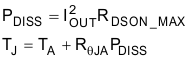
The steps that lead to calculating the junction temperature, TJ, begins with the worst-case power dissipation of the device. This requires the operating output current of the device, IOUT, and maximum on-resistance, RDSON (found in the Electrical Characteristics section of the data sheet of the device and denoted by the T = 150°C test condition). Once the power dissipated, PDISS, in the switch is calculated, junction temperature, TJ is calculated as a function of the power dissipation, PDISS, the ambient temperature, TA, of the surrounding environment, and the junction-to-ambient thermal resistance, RꝊJA, located in the thermal information section of the data sheet.
As an alternate, more accurate method, this document uses the electrical simulation software, PSpice, to model the thermal behavior of the high-side switch.
Ohm’s law defines the relationship where voltage, V, is equal to the product of current, I, and resistance, R. The power law explains that power, P, is equal to the product of voltage, V, and current, I.

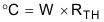
These laws can be used as an analogy for the transient thermal behavior in high-side switches. Equation 2 can be equivalently evaluated as resistance, R, is equal to the division of voltage, V, and current, I. Since thermal resistance, RTH, is measured in units of degrees Celsius, ᵒC, per watt, W, this relationship can be equivalently evaluated as temperature in Celsius equals the product of thermal resistance and power in watts as shown in Equation 3.
Seeing that voltage and temperature are both similarly proportional to a variable representing impedance or resistance, these two equations help in incorporating heat circuits’ theory and a model can be created. The model utilizes the analogy between thermal and electrical units in a one-to-one relationship, as described in Table 1-1.
|
Thermal |
Electrical |
|---|---|
|
Power (W) |
Current (A) |
|
Ambient Temperature (ᵒC) |
DC Voltage (V) |
|
Junction Temperature (ᵒC) |
AC Voltage (V) |
|
Thermal Resistance (ᵒC/W) |
Resistance (V/A = Ω) |
|
Thermal Capacitance |
Capacitance (F) |
In a thermal environment two inputs are apparent: power, PDISS, and ambient temperature, TA, creating one output: junction temperature, TJ. To translate this equation to electrical tools, the ambient temperature would be represented as a DC voltage source on the switch, and the power as an input current waveform to the switch, with temperature variation in the junction be represented by an RC ladder or network.
In an electrical environment, the thermal behavior is represented as an RC ladder as shown in Figure 1-1.
 Figure 1-1 Electrical Representation of Thermal
Environment
Figure 1-1 Electrical Representation of Thermal
EnvironmentIn this setup, thermal units are converted to electrical units as described in Table 1-1. The input power pulse is converted to a current source, the input ambient temperature is converted to a voltage source, and the high-side switch is converted to an RC representation of the thermals characteristics of the switch. These RC values are selected so that the resistances add up to RθJA and the capacitances represent the different paths heat will travel within the package.