SLVAEZ2 September 2020 – MONTH TPSM41625
1 Introduction
The TPSM41625 is a fixed frequency buck power module that uses an internally compensated Advanced Current Mode (ACM) control scheme intended to simplify the design process. While the ACM scheme in TPSM41625 offers a ramp selection feature to tune the gain of the loop response, the fixed power stage inductor in the module and the finite internal compensation options result in minimum requirements on the output capacitor network for stable operation.
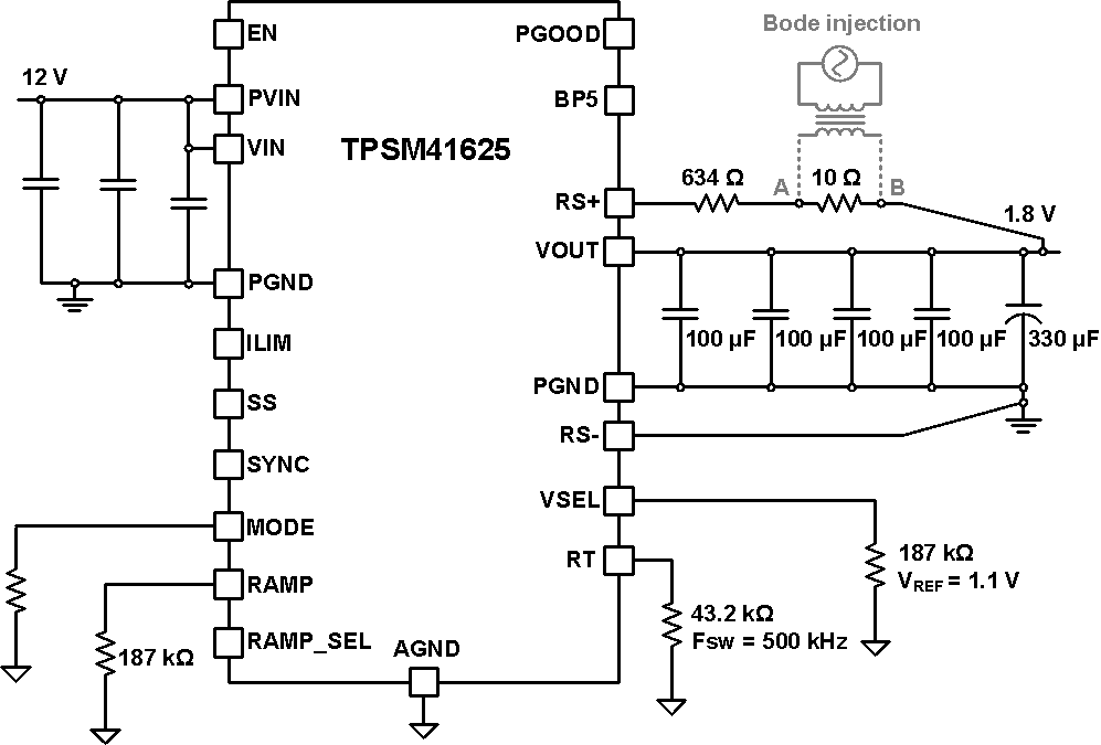
This application report will demonstrate how a combination of TPSM41625 ramp and reference settings, along with an external feedforward capacitor, can enhance the phase and gain margin of all ceramic, minimized output capacitor designs. While this report does not delve into the internal details of ACM control (1), measured loop response data is provided for an example design to illustrate the effect of output capacitance, ramp setting, and other design factors on TPSM41625 loop stability. Figure 1-1 shows the schematic of a 12-V input, 1.8-V output, 25-A, 500-kHz rail that is taken as the starting point for the design.

Figure 1-1 Original 12-V input, 1.8-V output, 25-A, 500-kHz design