SLVAEZ2 September 2020 – MONTH TPSM41625
3 Effect of Ramp Setting on Loop Response
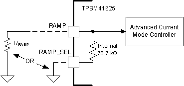
The TPSM41625 provides RAMP and RAMP_SEL pins which can be used to program the internal ramp and tune the loop response. With the RAMP_SEL pin left open, an external resistor connected between RAMP and AGND sets the internal ramp. Connecting RAMP_SEL to AGND and leaving RAMP pin open will select the internal 78.7-kΩ resistor such that no external resistor is required. Figure 3-1 shows these connection options.

Figure 3-1 Ramp connection options

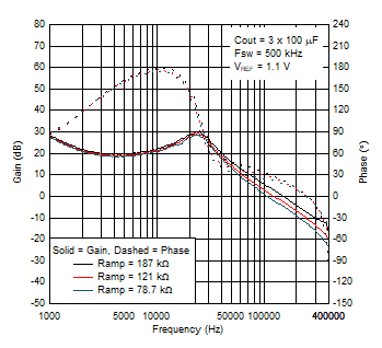
Figure 3-2 Bode plot for different ramp setting (12-V input, 1.8-V output)
The loop response for three different ramp settings is shown in Figure 3-2 for the 300-μF ceramic output capacitor configuration introduced in the previous section. As shown in the figure, decreasing the ramp resistor from 187 kΩ (the original value) to the lower options decreases the loop crossover frequency. A lower ramp resistor selects a lower internal ramp capacitor, which lowers the gain curve and thus the crossover frequency. With the internal 78.7-kΩ resistor selected, the crossover frequency has decreased from 148 kHz to 105 kHz and the gain margin has improved from 8 dB to 12.5 dB. However, in this case the phase curve has also shifted such that the phase margin is 24.5°, only a minor improvement compared to the 23° of phase margin with the 187-kΩ ramp setting. The following sections explore methods to increase the phase margin of this design with the internal 78.7-kΩ resistor selected.