SLVUBX1 December 2020 TPS63810
8.3 Schematic
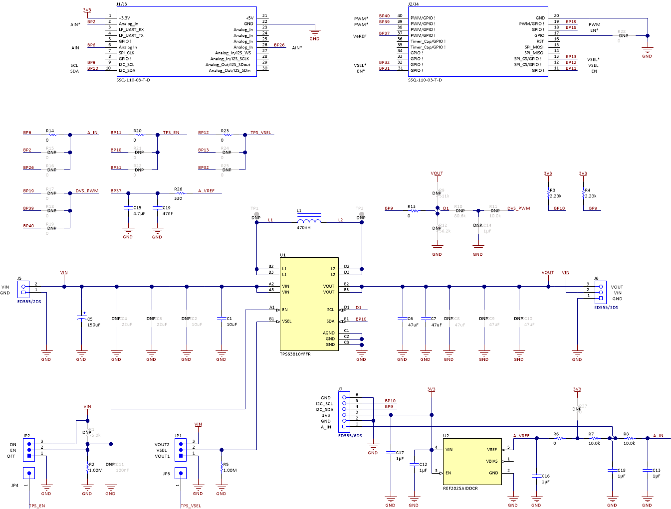
Figure 8-4 shows the BOOSTXL-TECDRV schematic. Note that some lines can be connected to different pins on the BoosterPack header. This is done so that the BoosterPack can be used with other TI LaunchPads. For example, the A_IN line used to interface the analog temperature sensor to the ADC on the LaunchPad is connected to the header pin BP6 via jumper resistor R14. If needed, this line can be re-routed to BP2 or BP26 pins of the BoosterPack header by removing R14 and populating R15 or R16 jumper resistors.
 Figure 8-4 BOOSTXL-TECDRV
Schematic