SLVUBZ4 February 2021 TPS25750
2.2 Filling Out The Form
The form is the main component in the center of the tool. Many questions on the form can be answered by selecting the desired option. Other questions require text input, whose format is specified by the question itself. Some questions may also be disabled based on answers to the other questions. After sufficiently completing the form, the options to generate a binary or flash the device on the right side panel will be enabled.
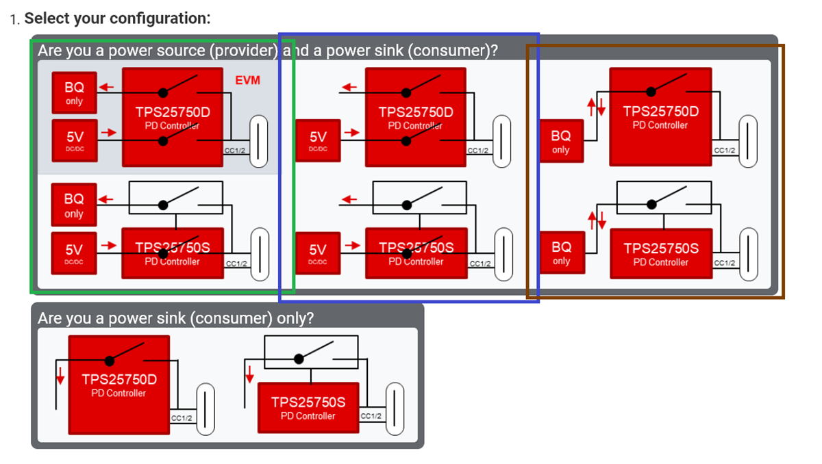
The first question of the form asks to select a configuration that the TPS25750 is used for. There are two main categories of possible configurations that device can act as: a power source and a power sink, or a power sink only. Each of these two main categories have multiple possible configurations. See Figure 2-2 below for how this question appears.
 Figure 2-2 First question of the form
In the category where the device acts as a power source and power sink, one set of options is that the device is sourcing power from a 5 V DCDC converter, and sinking power through a BQ device (battery charger). This set is outlined in green in Figure 2-2, appears on the left side of the category, with the TPS25750D variant on the top and the TPS25750S variant on the bottom.
Another set of options is that the device is sourcing power from a 5 V DCDC converter, and sinking power through a non-BQ device. This set is outlined in blue in Figure 2-2, appears in the middle of the category, with the TPS25750D variant on the top and the TPS25750S variant on the bottom.
The final set of options in the category is that the device is sourcing and sinking power from a BQ device (battery charger). This set is outlined in brown in Figure 2-2, appears on the right side of the category, with the TPS25750D variant on the top and the TPS25750S variant on the bottom.
The second category, where only power sinking is configured, there are only two options: the use of the TPS25750D variant, which appears on the left, and the use of the TPS25750S variant, which appears on the right.
The following two questions ask what the maximum power that can be sourced or sinked is. If there is no source configured, then the question asking for the maximum source power will be disabled.
The following two questions ask for the preferred data role and the preferred power role of the device.
The sixth question asks what the highest data speed standard the device should support. If no USB data is being used, then that option should be selected.
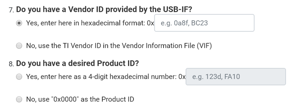
The next two questions ask for the Vendor ID and the desired Product ID, respectively. The Vendor ID should be given by the USB-IF, whereas the Product ID is simply a configuration identifier. If you wish to enter your own values for these questions, first select the Yes option for those questions, and fill in the corresponding text box using a 4-digit hexadecimal number. See Figure 2-3 below for what these questions look like.
 Figure 2-3 Vendor ID and Product ID
questions. An enabled text field is shown on top, while a disabled text field is
shown on the bottom
Figure 2-3 Vendor ID and Product ID
questions. An enabled text field is shown on top, while a disabled text field is
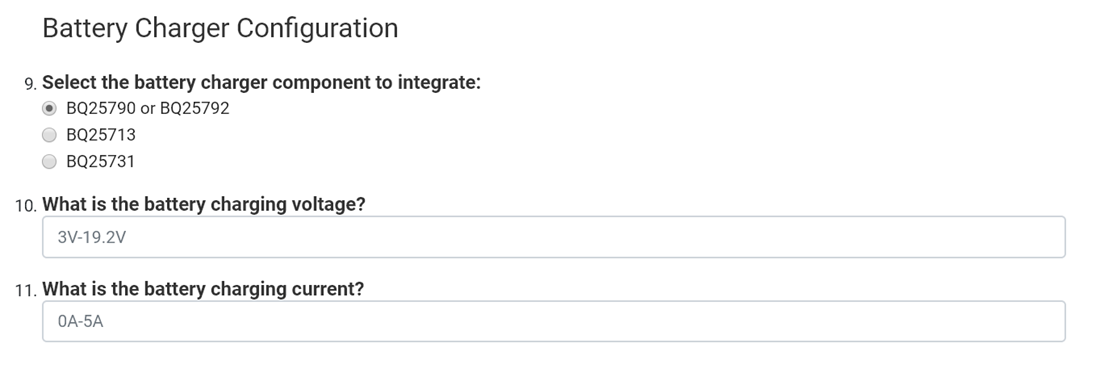
shown on the bottomThe last set of questions correspond to configuring the BQ device (battery charger). If a configuration in the first question is chosen such that no BQ device is being used, these questions will be disabled. The first question asks which BQ device is being used. The next two questions asks what the battery charger voltage and current should be. When entering the battery charger voltage or current, the range of valid numbers are displayed on the placeholder to the text box. The number entered should either be a whole number, or a decimal number specified to the hundredths place (for example, 16.18). An optional V for the voltage question or A for the current question can be added at the end of the number as well. See Figure 2-4 for what these questions look like.
 Figure 2-4 View of the battery charger
questions