SLVUCE2 May 2022
3.4.1 Connection Status
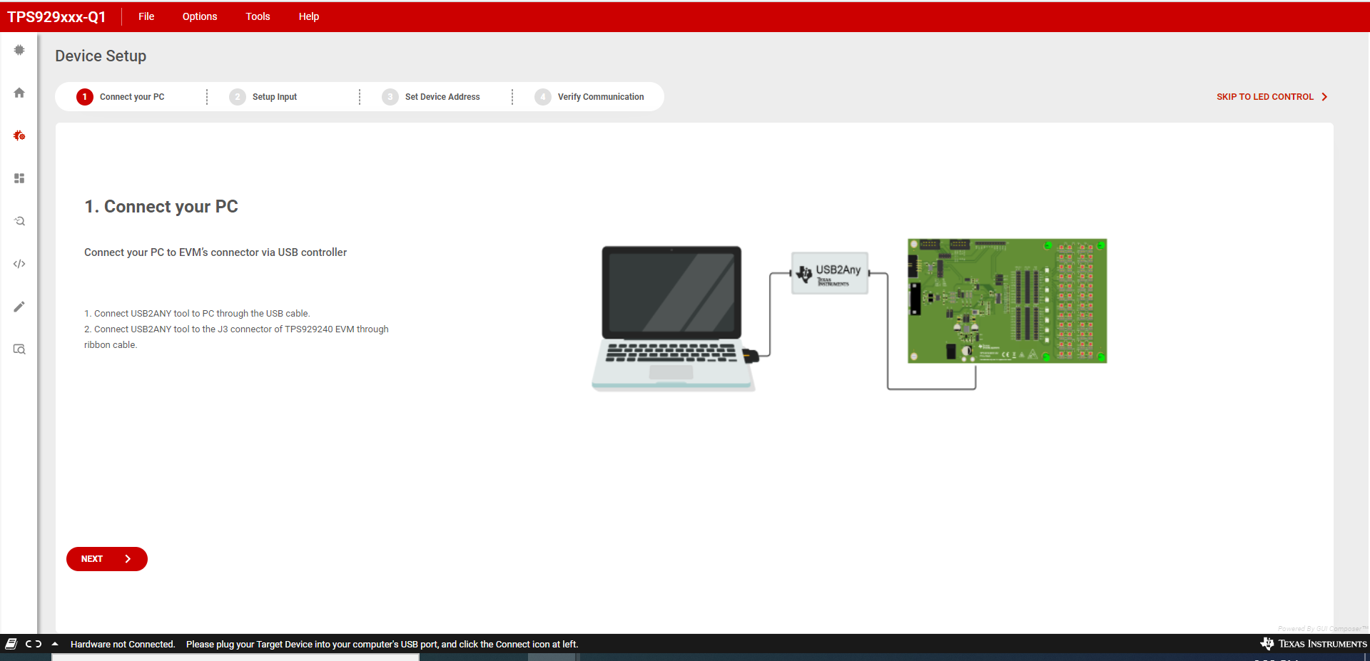
Make sure to power up the EVM board and connect it to the PC through USB2ANY tool before opening the on-line version GUI or desktop version GUI. If the GUI has been opened but the USB2ANY has not been connected to the PC, make sure the USB2ANY has been connected to the powered-up EVM board when plugging it into the PC. Other operation orders may lead to the GUI working abnormally. After this action happens, please refresh the on-line version GUI or re-run the desktop version GUI.
The GUI supports both hardware setups with CAN board connected or not connected. When CAN board connected, the CAN checkbox on the "Device Address" widget must be checked. When the CAN board is not connected, leave the CAN checkbox unchecked. Before changing hardware setup, remove the USB2ANY cable plug from PC.
Before using the GUI, make sure the hardware is connected successfully. Check the connection status on the home page where there is a green check mark on the left side of the TPS929240-Q1 body, which means the USB2ANY is connected to the computer successfully. If there is a red X mark, it means the hardware is not connected. Reconnect the device.
After hardware is connected, either "Hardware Connected" or "Hardware not Connected" shows on the bottom left corner of the GUI. The button to connect or disconnect the GUI to hardware is also available there. Click the button to connect to hardware if hardware is not connected or to disconnect from hardware while hardware connected.
To connect the GUI to device successfully, set the correct device address on the GUI to map the real device address. See the TPS929240-Q1 12-Channel Automotive 40-V High-Side LED Driver with FlexWire data sheet for instructions to set the device address. The default device address setting value of the GUI is 0x01 when you open the GUI.
On the EVM board, the ADDR0, ADDR1 and ADDR2 can be configured as High or Low through "J5", "J8" and "J11" connectors. On the GUI page you can directly enter the specified value through the "Device Address" widget.
 Figure 3-11 TPS929240EVM GUI Connection
Status