SLWU067D November 2009 – March 2022 ADS4122 , ADS4125 , ADS4126 , ADS4128 , ADS4129 , ADS4142 , ADS4145 , ADS4146 , ADS4149 , ADS41B25 , ADS41B29 , ADS41B49 , ADS58B18 , ADS58B19
5.1 Register Programming
Early EVMs (serial number 001 to 050) were assembled with preproduction silicon. To obtain optimum SNR and SFDR performance at input frequencies above 130 MHz, it is recommended to set the following registers:
| Address | Data |
|---|---|
| x03 | x04 |
| xD3 | x40 |
| xDB | xD0 |
This change is addressed in production silicon.
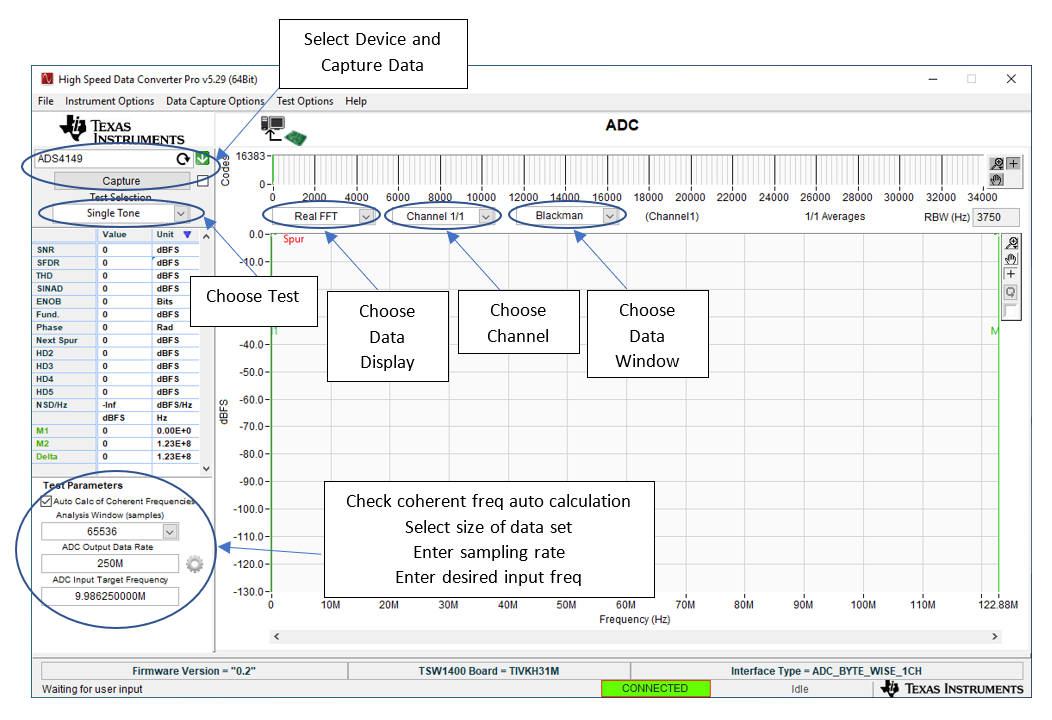
 Figure 5-1 TSW1400 GUI Introduction
To start the evaluation with the High Speed Data Converter Pro software, note the following points:
- Open High Speed Data Converter Pro by going to Start Menu → All Programs → Texas Instruments → High Speed Data Converter Pro.
- When prompted to select the capture board, select the TSW1400 whose serial number corresponds to the serial number on the TSW1400EVM and click OK. This pop-up can also be accessed via Instrument Options → Connect to the Board when not already connected to a board.
- When prompted to select a device, select ADC in the drop-down menu.
- If no firmware is currently loaded, there is a message indicating this. Click on OK.
- Use the Select ADC drop-down menu at the top left corner to select the device under test.
- When prompted to update the firmware for the ADC, click Yes and wait for the firmware to download to the TSW1400. This takes a couple of seconds.
- Enter the desired output data rate into the ADC Output Data Rate field at the bottom left corner then click outside this box or press Return on the PC keyboard to update.
- Click Capture in HSDC Pro to capture data from the ADC.
- Adjust the input level signal to attain the dBFs of approximately -1.