SNAU260A October 2020 – February 2021 LMK5C33216
ADVANCE INFORMATION
- Trademarks
- 1Introduction
- 2EVM Quick Start
- 3EVM Configuration
-
4EVM Schematics
- 4.1 Power Supply Schematic
- 4.2 Power Distribution Schematic
- 4.3 LMK5C33216 and Input Reference Inputs IN0 to IN1 Schematic
- 4.4 Clock Outputs OUT0 to OUT3 Schematic
- 4.5 Clock Outputs OUT4 to OUT9 Schematic
- 4.6 Clock Outputs OUT10 to OUT15 Schematic
- 4.7 XO Schematic
- 4.8 Logic I/O Interfaces Schematic
- 4.9 USB2ANY Schematic
- 5EVM Bill of Materials
- 6Appendix A - TICS Pro LMK5C33216 Software
- 7Revision History
6.3.1 Cascaded Configurations
Cascaded configurations can be created using the input page, where the relevant VCO buffers and dividers will automatically be enabled by inferring the state of source selection registers.
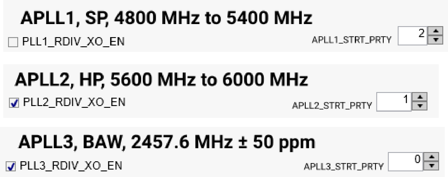
At least one PLL must always be active and set to XO reference source for cascaded configurations to be valid. APLL start-up priority will automatically choose XO-source APLLs to start up before all other PLLs whenever possible. If in pin-selection mode, since start-up priority cannot be properly inferred, users must set this priority themselves in the User Controls page. In the example image below, APLL2 and APLL3 are referenced to XO input and APLL1 reference is from APLL3. Priority is controlled in ascending order, with 0 first and 2 last. APLLs can share priorities; if all APLL priorities are set to 0, all APLLs will startup simultaneously.
 Figure 6-11 Cascade
APLL Start Priorities.