SNLA438 September 2023 DP83822H , DP83822HF , DP83822I , DP83822IF , DP83826E , DP83826I , DP83867CS , DP83867E , DP83867IS , DP83869HM
3.1.1 DP83822 Hardware Bootstrap Configurations
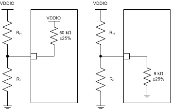
The DP83822 uses certain pins as bootstrap options to place the device into specific modes of operation. The values of these pins are sampled at power up or hardware reset, providing a way to configure the device into a desired mode without the need for software configuration.
 Figure 3-2 Bootstrap Circuit
| DP83822 100Base-TX Strapping | Pin | RH(kΩ) | RL(kΩ) | Remarks |
|---|---|---|---|---|
|
PHY Address: 1, MAC Interface: MII, 10/100 Mbps Full Duplex Advertised, Copper, Auto-negotiation Enabled, Auto-MDIX Enabled, FLD Enabled, |
COL | Open | Open |
Copper PHY_ADD0[1] |
| RX_D0 | Open | Open | PHY_ADD1[0] | |
| RX_D1 | Open | Open |
EEE disable PHY_ADD2[0] |
|
| RX_D2 | 10 | 2.49 |
FLD Enabled PHY_ADD3[0] |
|
| RX_D3 | Open | Open | Auto-Negotiation Enabled | |
| LED_0 | Open | Open |
Advertised Full Duplex 10Base-Te/100Base-TX |
|
| LED_1 | Open | Open | No Added Functionality Do not use Mode 2 & 3 |
|
| RX_ER | Open | Open |
MII Auto-MDIX Enable |
|
| RX_DV | Open | Open | MII |
| DP83822 100Base-FX Strapping | Pin | RH(kΩ) | RL(kΩ) | Remarks |
|---|---|---|---|---|
|
PHY Address: 1, MAC Interface: MII, 10/100 Mbps Full Duplex Advertised, Fiber, Auto-negotiation Enabled, Auto-MDIX Enabled, FLD Enabled, |
COL | 13 | 1.96 |
Fiber Enabled PHY_ADD0[1] |
| RX_D0 | Open | Open | PHY_ADD1[0] | |
| RX_D1 | Open | Open |
EEE disable PHY_ADD2[0] |
|
| RX_D2 | 10 | 2.49 |
FLD Enabled PHY_ADD3[0] |
|
| RX_D3 | Open | Open | Auto-Negotiation Enabled | |
| LED_0 | Open | Open |
Advertised Full Duplex 10Base-Te/100Base-FX |
|
| LED_1 | Open | Open |
No Added Functionality Do not use Mode 2 & 3 |
|
| RX_ER | Open | Open |
MII Auto-MDIX Enable |
|
| RX_DV | Open | Open | MII |