SNLU254A November 2020 – July 2022
3.4 EEPROM Page
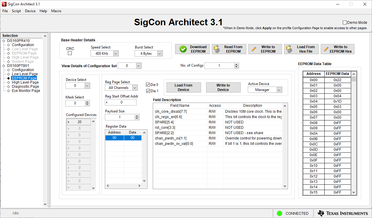
 Figure 3-3 EEPROM Page Screenshot
The EEPROM page provides access to the EEPROM reading and writing functions of the retimer. It also allows a user to load or save a pre-configured EEPROM image stored in the .hex file format. For more details about EEPROM image formatting, please refer to the DS160PT801 EEPROM Programming Guide.(1)
- CRC Check Box sets the CRC bit to "1" in the EEPROM base header. If enabled, CRC value is computed for all configuration sets and CRC checking is performed.
- Speed Select Dropdown modifies the write speed field in the EEPROM base header for the current EEPROM image. This effects how quickly the EEPROM is loaded after power-up.
- Burst Select Dropdown modifies the EEPROM base header to change the amount of consecutive bytes per read when loading an EEPROM image.
- Download EEPROM Button initiates a download of the currently loaded image on the EEPROM to the retimer.
- Read From EEPROM Button reads the currently loaded EEPROM image and updates the GUI with its contents.
- Write to EEPROM Button writes the EEPROM configuration that is currently active in the GUI to the EEPROM device.
- Load From Hex File Button opens a file explorer window that allows the user to load a .hex file EEPROM image.
- Write to EEPROM Hex Button saves the currently loaded configuration in the GUI to a .hex file EEPROM image.
- View Details of Configuration Set Dropdown selects the current EEPROM Configuration Set that is displayed and can be edited in the GUI.
- No. of Configs Field shows the maximum number of configuration sets for the current configuraiton
- Device Select Dropdown, combined with the Mask Select dropdown, modifies the SMBus addresses that are effected by the currently displayed configuration set.
- Mask Select Dropdown, combined with the Device Select dropdown, modifies the SMBus addresses that are effected by the currently displayed configuration set.
- Configured Devices List shows SMBus addresses of the retimers that will be effected by the currently displayed configuration set.
- Reg Page Select Dropdown modifies the register page for the currently displayed configuration set.
- Reg Start Offset Addr Dropdown modifies the starting register offset address for the currently displayed configuration set.
- Payload Size Dropdown determines the number of bytes to be written in the currently selected configuration set. The bytes will begin writing at the location specified by the Reg Start Offset Addr Dropdown.
- Register Data Table displays the SMBus addresses and corresponding values in the currently selected configuration set.
- Die 0 Checkbox enables Die 0 to be written to by the currently selected configuration set.
- Die 1 Checkbox enables Die1 to be written to by the currently selected configuration set.
- Load From Device Button updates the current configuration set's data with the register settings of the active device.
- Write to Device Button updates the register settings of the active device with the current configuration set's data.
- Active Device Dropdown changes the active device for the Load From Device and Write to Device commands.
- Field Description Table shows the register map information about the currently selected register.
- EEPROM Data Table shows the full raw EEPROM data that will be loaded on the retimer.
1. The DS160PT801 EEPROM Programming Guide is available upon
request.