SNLU254A November 2020 – July 2022 DS160PT801
3.5 Control Panel
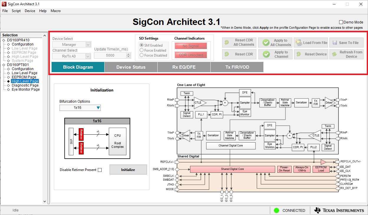
 Figure 3-4 Control Panel Screenshot
The retimer control panel is present in the High-Level, Diagnostic, and Eye Monitor pages of the DS160PT801 GUI. Based on the page that a user is currently on, it will enable and disable certain functions. A list of the functions for each of the fields within the control panel is shown below:
- Device Select Dropdown selects the active device being configured, either the link-width manager or link-width follower. It is enabled in the High-Level page when modifying the Rx/Tx EQ settings, the Diagnostic page, and Eye Monitor pages.
- Channel Select Dropdown selects the active channel being configured. It is enabled in the High-Level page when modifying the Rx/Tx EQ settings, the Diagnostic page, and Eye Monitor pages.
- Update Time Dropdown updates the refresh rate for the GUI when the GUI is automatically polling for retimer status information, such as the Device Status section of the High-Level page.
- SD Settings Radio Buttons changes the Signal Detect mode of the currently selected channel between State Machine controlled, Force Enabled, and Force Disabled.
- Channel Indicators reports if the currently active channel is detecting a signal and if the CDR is locked onto the incoming signal.
- Reset CDR All Channels Button reset the CDR for all channels on the currently active device. This will break a PCIe link and should be used for evaluation only.
- Apply to All Channels Button applies changes specified in the GUI to all channels on the retimer. It is enabled in the High-Level page when modifying the Rx/Tx EQ settings, the Diagnostic page, and Eye Monitor pages.
- Load From File Button allows a user to load a previously saved configuration file.
- Save to File Button enables a user to save the current SMBus configuration for the retimer in a configuration file.
- Reset CDR Button resets the CDR for the currently selected channel.
- Apply to Channel Button applies signal detect settings to the currently selected channel.
- Reset Device Button completely resets the retimer to the default register settings. This will disable a PCIe link.
- Refresh From Device Button refreshes data in the GUI by downloading the current SMBus configuration of the retimer.