SNOU143 February 2017 EMB1428Q , EMB1499Q
4.1.1 Battery Connector
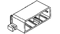
The battery cell connections are made from connector J1. Cell voltage measurements and balancing currents use these connections. Short unused channels to the top cell connection in the wiring harness to support less than 16 cells.
 Figure 2. Tyco Electronics 175785-1 (Reference Image Only)
 Table 1. Connector Information
| Designator | Manufacturer | Part Number | Mating Connector |
|---|---|---|---|
| J1 | Tyco Electronics | Manufacturer: 175785-1
Digi-Key: 175785-1-ND |
Manufacturer: 174952-1
Digi-Key: 1-174952-1-ND Contacts: Manufacturer: 175027-6 (16-20 AWG) Digi-Key: 175027-6-ND |
Table 2. Pin Description
|
|
||
| Pin | Name | Comments |
| 1 | BAT16 | Positive terminal of BAT16 |
| 2 | BAT13 | Positive terminal of BAT13, negative terminal of BAT14. |
| 3 | BAT12 | Positive terminal of BAT12, negative terminal of BAT13. |
| 4 | BAT11 | Positive terminal of BAT11, negative terminal of BAT12. |
| 5 | BAT10 | Positive terminal of BAT10, negative terminal of BAT11. |
| 6 | BAT5 | Positive terminal of BAT5, negative terminal of BAT6. |
| 7 | BAT4 | Positive terminal of BAT4, negative terminal of BAT5. |
| 8 | BAT3 | Positive terminal of BAT3, negative terminal of BAT4. |
| 9 | BAT0 | Negative terminal of BAT1. Local ground for module. |
| 10 | BAT15 | Positive terminal of BAT16, negative terminal of BAT16. |
| 11 | BAT0 | Negative terminal of BAT1. Local ground for module. |
| 12 | BAT14 | Positive terminal of BAT14, negative terminal of BAT15. |
| 13 | NC | Not connected |
| 14 | BAT9 | Positive terminal of BAT9, negative terminal of BAT10. |
| 15 | BAT8 | Positive terminal of BAT8, negative terminal of BAT9. |
| 16 | BAT7 | Positive terminal of BAT7, negative terminal of BAT8. |
| 17 | BAT6 | Positive terminal of BAT6, negative terminal of BAT7. |
| 18 | BAT1 | Positive terminal of BAT1, negative terminal of BAT2. |
| 19 | BAT16 | Positive terminal of BAT16 |
| 20 | BAT2 | Positive terminal of BAT2, negative terminal of BAT3. |