SNOU176B October 2020 – March 2022
PRODUCTION DATA
- Trademarks
- 1 General TI High Voltage Evaluation User Safety Guidelines
- 2 Introduction
- 3 LMG342XEVM-04X Schematic
- 4 Mother Board Schematic
- 5 Recommended Footprint
- 6 Test Equipment
- 7 Test Procedure When Paired With LMG342X-BB-EVM
- 8 Test Procedure When Paired With LMG34XX-BB-EVM
- 9 Bill of Materials
- 10Revision History
7.2 Start-Up and Operating Procedure
- Turn on +12VDC to the LMG342X-BB-EVM. Watch the power supply for the DC current to settle down after approximately 3 to 5 seconds.
- Make sure all the fault LEDs are off and the 5-V LED is on.
- Turn on +12VDC to enable the fan.
- Turn on the function generator to output the continuous pulse, and check the deadtime of the PWM signals.
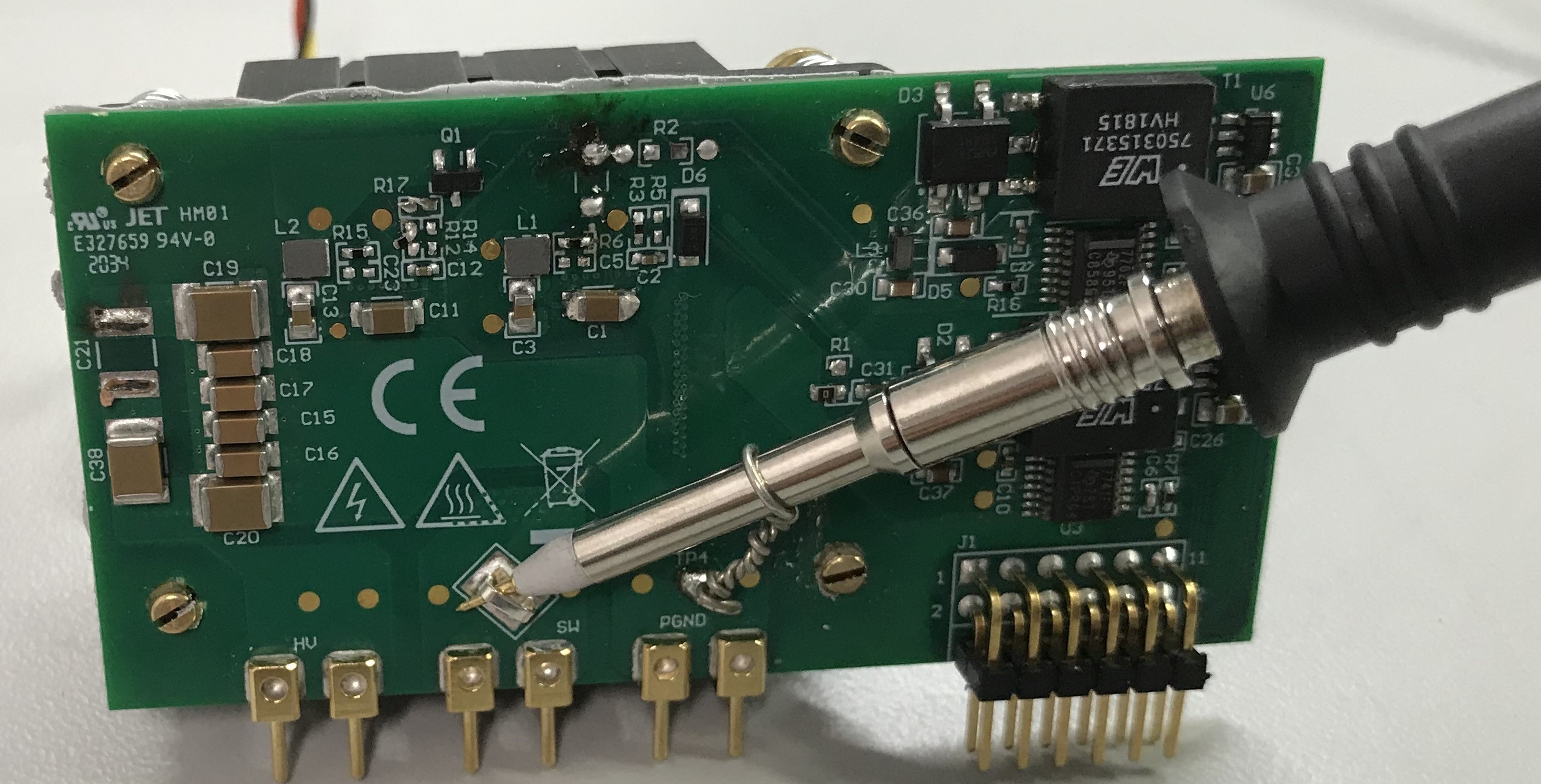
User proper probes for measurement. To measure the fast switching transient in the switch-node, it is recommended to use the high-bandwidth high-voltage passive probes with minimized ground loop connections.
It is recommended to add common-mode chokes to the measurement signals and to the power input/output connections.
- Enable the high voltage power supply and make sure to ramp the voltage up gradually from 0V to the desired bus voltage (up to 480V). As the voltage is ramping up, the HV LED will turn on and become brighter.
 Figure 7-3 Switch-Node Voltage Measurement with
High-Bandwidth Probe and Pigtail Ground Connection
Figure 7-3 Switch-Node Voltage Measurement with
High-Bandwidth Probe and Pigtail Ground ConnectionWARNING:
Do NOT turn on the device at the absolute maximum voltage. TI recommends to start the device at or below 480 V. Slowly increase the input voltage and monitor the VSW to ensure the peak voltage does not exceed the absolute maximum rating of 600 V.