SNVAA25A January 2022 – July 2022 DP83TD510E , ESDS302 , LM5155 , LM66100 , MSP430FR2476 , TL431LI , TLV3012
3.1 PD Design Overview
It is important to understand the functions of both the PD and PSE before designing the PoDL system. The PSE has 4 main functions according to the IEEE standards. From the IEEE 802.3bu standard, the main functions of the PSE include:
- To search the link segment for a PD
- To supply power to a detected PD through the link segment
- To monitor the power applied to a link segment
- To remove the full operating voltage when no longer required, or when a short-circuit or other fault is detected
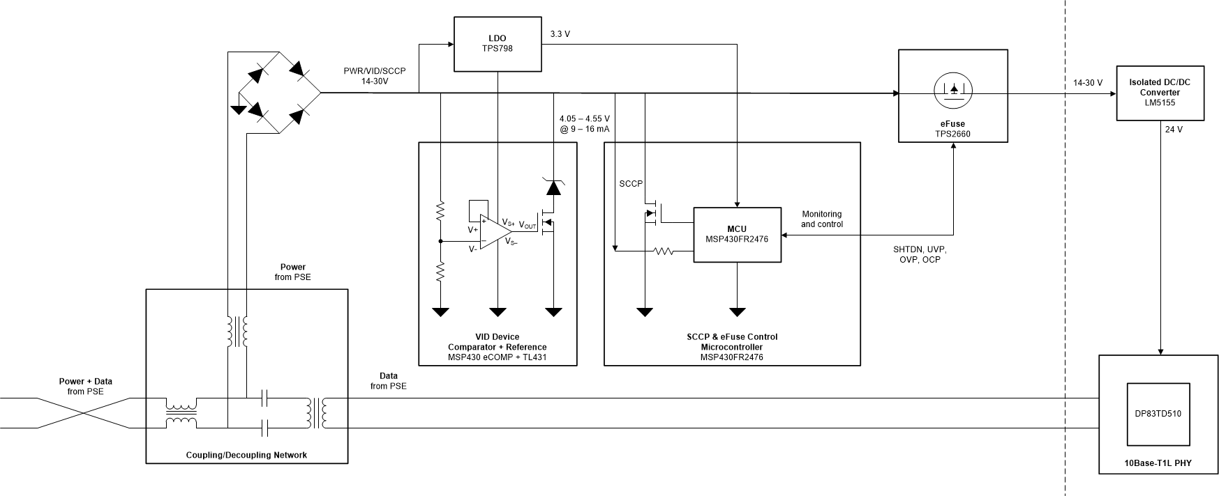
Conversely, the PD, is simply the portion of a device that draws power from the link or the portion that participates in the detection or classification algorithms. The PD system presented in this document includes:
- The coupling and decoupling network (CDN) which decouples power from the power and data path
- The VID block required for the PD to be detected as PoDL-compliant to a PSE
- SCCP communication necessary for the optional classification function for power class negotiation
- Power protection and regulated and isolated 24-V class-12 power supply to the device being powered
Figure 3-1 shows these system blocks.

Figure 3-1 PoDL PD System Block Diagram