SPRADF4 December 2023 TMS320F280023C , TMS320F280025C , TMS320F280025C-Q1 , TMS320F280037C , TMS320F280037C-Q1 , TMS320F280039C , TMS320F280039C-Q1 , TMS320F280049C , TMS320F280049C-Q1 , TMS320F28377D , TMS320F28377D-EP , TMS320F28377D-Q1 , TMS320F28377S , TMS320F28377S-Q1 , TMS320F28379D , TMS320F28379D-Q1 , TMS320F28379S , TMS320F28P650DK
1 Introduction
LLC resonant converters are becoming increasingly popular in industrial power applications. To achieve higher efficiency, the rectification diodes are replaced with MOSFETs to reduce conduction losses. A common practice is to use digital control for LLC converters for flexibility and scalability, especially in high-power applications. Application users must currently compare the switching and resonant frequencies in real-time, as discussed in Intelligent LLC SR Control Using C2000™ and UCD7138. For example, clamping the SR PWM on-time is required if the present switching frequency is below the resonant frequency. Otherwise, turning off the SR PWM following the primary-side PWM is required. Since the SR control requires fast response for reliability considerations, the software comparison can be placed in high frequency ISR, which takes up part of the CPU bandwidth.
Current-mode LLC is increasingly popular for solving the load-transient challenge using traditional voltage-mode control. However, defining the on time for SR PWM as preceding the comparator event using normal EPWM configuration is impossible because the comparator sets the turn-off timing of the primary-side PWM for current-mode LLCs using digital control. This document introduces a new way of implementing the SR control by leveraging the CLB module in the latest generation of C2000™ microcontrollers. This document also provides examples of implementing CLB in actual applications. These detailed configurations and example codes are based on the F28003x series, which applies to any C2000™ devices with the CLB module.
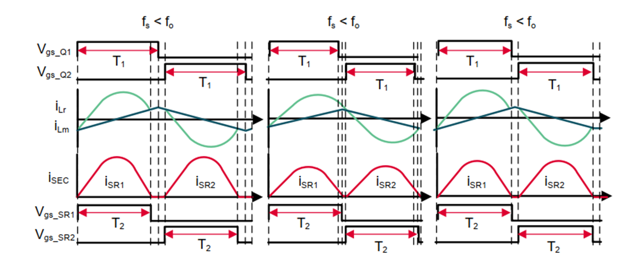
The desired SR driving signal under different switching frequencies (fS) is given in Figure 1-1. To achieve adequate SR control, the below control targets normally achieve correct SR control:
- Hardware-based SR control without the software switch between the SR clamp mode (fS < fo) and resonant mode (fS > fo)
- Adjustable SR PWM turn-on delay
- Adjustable SR PWM clamping time
- Add the turn-off delay for SR PWM during resonant mode (optional)
 Figure 1-1 Desired SR Driving Signal Under
Different fS