SPRUIT8D February 2020 – February 2021 AWR2243
- Trademarks
- 1Getting Started
- 2Hardware
- 3Design Files and Software Tools
- 4Design Revision History
- 5Mechanical Mounting of PCB
- 6PCB Storage and Handling Recommendations
- 7Regulatory Information
- 8Revision History
2.7.3 Push Buttons and LEDs
Table 2-5 and Table 2-6 list the push button and LED uses, respectively.
Table 2-5 Push Buttons
| Reference | Use | Comments | Image |
|---|---|---|---|
| SW2 | RESET | This button is used to reset the radar device. This signal is also brought out on the 20-pin connector and 60-pin HD connector, so that an external processor can control the AWR device.
The onboard XDS110 can also use this reset. | 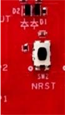 |
| SW1 | GPIO_1 | When this button is pushed, the GPIO_1 is pulled to Vcc. | 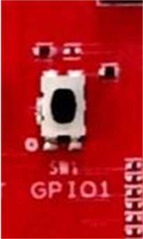 |
Table 2-6 LEDs
| Reference | Color | Use | Comments | Image |
|---|---|---|---|---|
| DS2 | Red | 5-V supply indication | This LED indicates the presence of the 5-V supply. | 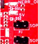 |
| DS4 | Yellow | nRESET | This LED is used to indicate the state of nRESET pin. If this LED is on, the device is out of reset. This LED glows only after the 5-V supply is provided. | 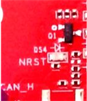 |
| DS1 | Red | NERR_OUT | This LED turns on if there is any hardware error in the AWR device. | 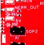 |
| DS3 | Yellow | GPIO_1 | This LED turns on when the GPIO is logic-1. | 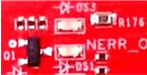
|