SWRA446 February 2015 CC1310 , CC1310 , CC2620 , CC2620 , CC2630 , CC2630 , CC2640 , CC2640 , CC2640R2F , CC2640R2F , CC2640R2F-Q1 , CC2640R2F-Q1 , CC2650 , CC2650 , CC2650MODA , CC2650MODA
6.1 Configure Flash Programmer Tool (Windows)
This section describes how to configure the SmartRF Flash Programmer tool for the Eclipse environment on Windows. The Flash programmer tool is used to load a generated binary image to the target before debugging.
- Start SmartRF Flash Programmer 2 GUI application (installation is described in Section 4.8).
- Start command line by clicking the tools symbol in the top right corner of the GUI.
- Make sure the hardware is connected on the USB and type srfprog –ls all in the command line to detect the connected hardware. If there is one SmartRF EB board connected on USB the output will be similar to the output shown in Figure 14.
- Write down the ID of the detected EB board (in the above example it is XDS-06EB12100376A).
- In Eclipse, navigate to Run → External Tools → External Tools Configurations.
- Right click on 'Program' in the left side panel and select 'New' to create a new Tools configuration.
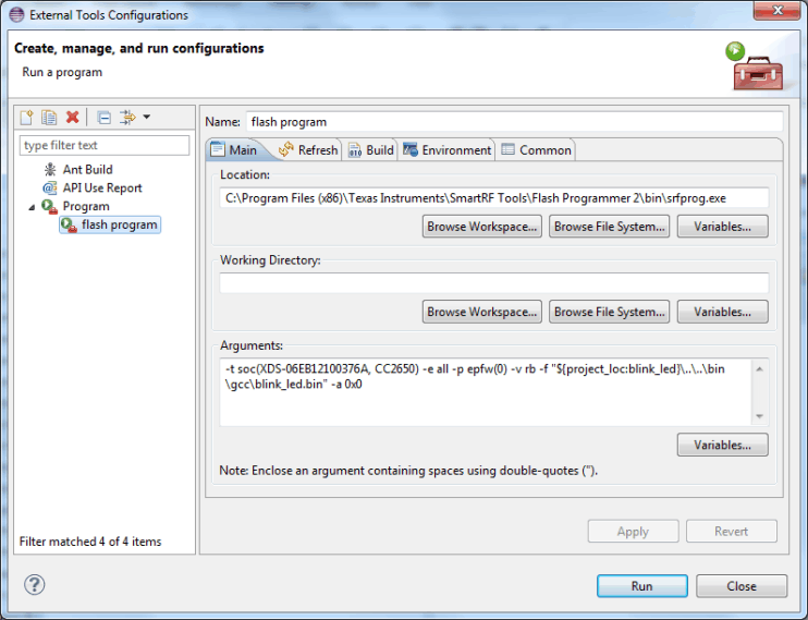
- Fill in the fields 'Name', 'Location' and 'Arguments' as shown in Figure 15.
- Location should be set to the directory where the SmartRF Flash programmer 2 was installed. The location below is correct when default installation directory is used.
- In the Arguments field, type in the following code:
-t soc(XDS-06EB12100376A, CC2650) -e all -p epfw(0) -v rb -f
"${project_loc:blink_led}\..\..\bin\gcc\blink_led.bin" -a 0x0
Make sure to use the same XDS ID number as noted in step 4.
What the command means is:
-t: specified target
-e all: Erase all pages
-p epfw(0): program, but exclude pages filled with 0x00
-v rb: verify using readback
-f: file to program
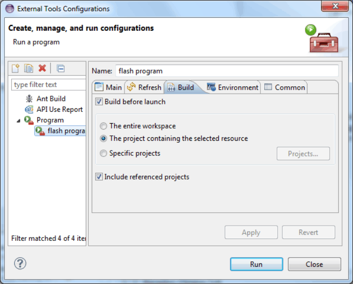
-a 0x0: start address is 0x00 - If you have several projects in your workspace, select the 'Build' tab, and choose to build 'The project containing the selected resource', instead of building the complete workspace (see Figure 16).
- Press 'Apply'.
- Each EB has its own ID, so if you change to another SmartRF EB board, repeat step 1 to 4 and change the ID used in the 'Arguments' field.
 Figure 14. Connected Devices
  Figure 15. Flash Programming Configuration
  Figure 16. Flash Programming Configuration