SWRA625B August 2018 – February 2020 CC1352P , CC1352R , CC2652P , CC2652R , CC2652R7 , CC2652RSIP
- Z-Stack End Device Power Consumption Measurement With the SimpleLink Wireless MCU Family
- Revision History
4.2.3 ZED Node
Open the workspace file zed_sw_CC26X2R1_LAUNCHXL_tirtos_ccs.projectspec with the correct version of CCS. The project file is found in the following folder after installing the SimpleLink CC13X2/CC26X2 SDK 3.10.00 [5]:
C:\ti\simplelink_cc13x2_26x2_sdk_<version>\examples\rtos\<LaunchPad>\zstack\zed_sw\tirtos\ccs
The power saving features (implemented in the Z-Stack for ZEDs) is not enabled by default, as it would hinder the debugging within the development phase. In order to enable these features for the measurement setup, the correct compile options must be set as well as adding several lines of code in the application files described below. For all details about the power saving functionalities, see the Power Management section in the Z-Stack User's Guide[6].
As already mentioned in the ZC Node setup, it is also important to ensure the NV_RESTORE predefine symbol is defined.
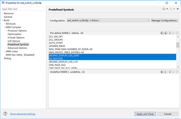
To modify the predefined symbols for the ZED project, right click on the project in Project Explorer, go to Properties → Build → ARM Compiler → Predefined Symbols. In order to define or un-define a value, use the convention of removing or adding a 'x' prefix to the value name, respectively. Ensure that the following values are defined/un-defined:
- xBOARD_DISPLAY_USE_UART
- NV_RESTORE
 Figure 5. Setting Compile Options for the ZED Node
 Additionally, there are a few code changes that are required. To make it easier to catch the measurements on the power analyzer, it may be useful to adjust the polling rate in the ZED, which determines how often the device wakes up from sleep and sends a data request to its parent to poll for pending data (queued messages). A poll rate of 1 second (default) has been used as shown in Figure 6, which is found inside Stack/Config/zstack_config.h.
 Figure 6. Setting up Poll Rate
 NOTE
In order to save power, increase the polling rate; however, be aware of the importance of the polling rate. In a Zigbee network, parents only keep the data buffered for their children for a certain time. Therefore, a ZED that sleeps too long would miss messages as they time out in its parent.
Polling can completely be disabled by setting the POLL_RATE to 0 (if the device should not receive data); however, this may lead to high latency as the device, when waking up, first must poll and if the parent is gone, the ZED must re-join the network again before it is able to send its data. This can take a long time, and become a problem if the network in the meantime changed channels or security key. For more details, see the Zigbee specification.
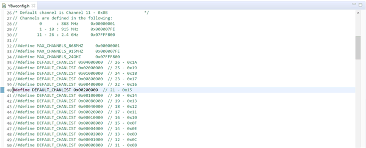
For all projects, the default channel (Channel 11) can be changed for the application inside the same file as shown in Figure 7. To do this, uncomment the desired channel to be the default, ensuring the rest of the channels are commented out. If using a different default channel, ensure all applications are configured with the same default channel set.
 Figure 7. Setting Custom Default Channel
 The next change is adding the functionality to change the TX power level when sending data packets. By default, the TX packets are sent out at 5 dBm power. To change the TX power level to a different value for a ZED, modify the function zclSampleSw_Init() inside the file Application/zcl_samplesw.c, adding the following lines:
...
//Setup ZDO callbacks
SetupZStackCallbacks();

// Setup power level
zstack_sysSetTxPowerReq_t powerReq;
zstack_sysSetTxPowerRsp_t powerRsp;
powerReq.requestedTxPower = 0; // 0 dBm

Zstackapi_sysSetTxPowerReq(appServiceTaskId, &powerReq, &powerRsp);
...
The powerReq.requestedTxPower is where the power level can be set in dBm. The maximum power level supported for a regular CC1352R/CC2652R device in IEEE 802.15.4 mode is 5 dBm. The CC1352P device includes an integrated Power Amplifier that can support up to 20 dBm. For 10 and 20 dBm power measurements taken in Section 5, a LAUNCHXL-CC1352P-2 is used. It can also be noted that this above code change can be used for any example project, and only requires changing the appServiceTaskId to the appropriate application's entity variable name.
Also remember to erase the flash when programming as shown in Figure 4 for the ZED.
To save current consumption even further on the LAUNCHXL-CC1352P-2, Boost Mode can be disabled, which is enabled in the TX power tables by default when the PA is enabled. Boost Mode increases the VDDR from 1.7 V to 1.95 V in order to increase the output power from the power amplifier further. This mode enables the CC1352P device to output at the full 20 dBm in 802.15.4 IEEE mode, whereas, without Boost Mode, the device will output 17 dBm with the maximum TX power level setting.
Boost Mode is enabled from inside the TX power tables. The TX power tables can be modified in the file found inside the following directory:
C:\ti\simplelink_cc13x2_26x2_sdk_<version>\source\ti\ti154stack\common\boards\mac_user_config_cc13x2r1_rftable.h
The list txPowerTable_ieee_CC1352P1 defines all available TX power levels available to be used when the PA is enabled. The RF_TxPowerTable_HIGH_PA_ENTRY define has the following structure:
RF_TxPowerTable_HIGH_PA_ENTRY(bias, ibboost, boost, coefficient, ldotrim)
To disable boost mode, set the boost value to 0 inside the TX power table for the desired TX power level entry. In this application report, the TX power entries for 10 and 20 dBm were modified to disable Boost Mode, as the CC2652R does not have Boost Mode enabled. For more information on Boost Mode, see the CC1352P Data Sheet[7].
As the final step, simply right click on the project in Project Explorer → Debug As → Code Composer Debug Session. This builds the project if any changes were done from the last time the project was built, and programs the LaunchPad connected with the ZED switch project.
Stop the debugger by pressing the red Terminate button (Ctrl+F2) and follow the instructions in Section 4.2.5 to establish a Zigbee network with the switch bound to the light, before disconnecting the ZED from the computer. Finally connect it to the DC Power Analyzer as shown in Figure 3.