SWRA662A January 2020 – September 2022 AWR1243 , AWR1443 , AWR1642 , AWR1843 , AWR1843AOP , AWR2243 , AWR6843 , AWR6843AOP , IWR1443 , IWR1642 , IWR1843 , IWR6443 , IWR6843 , IWR6843AOP
3.2 Different Starting Time for Parallel Interference
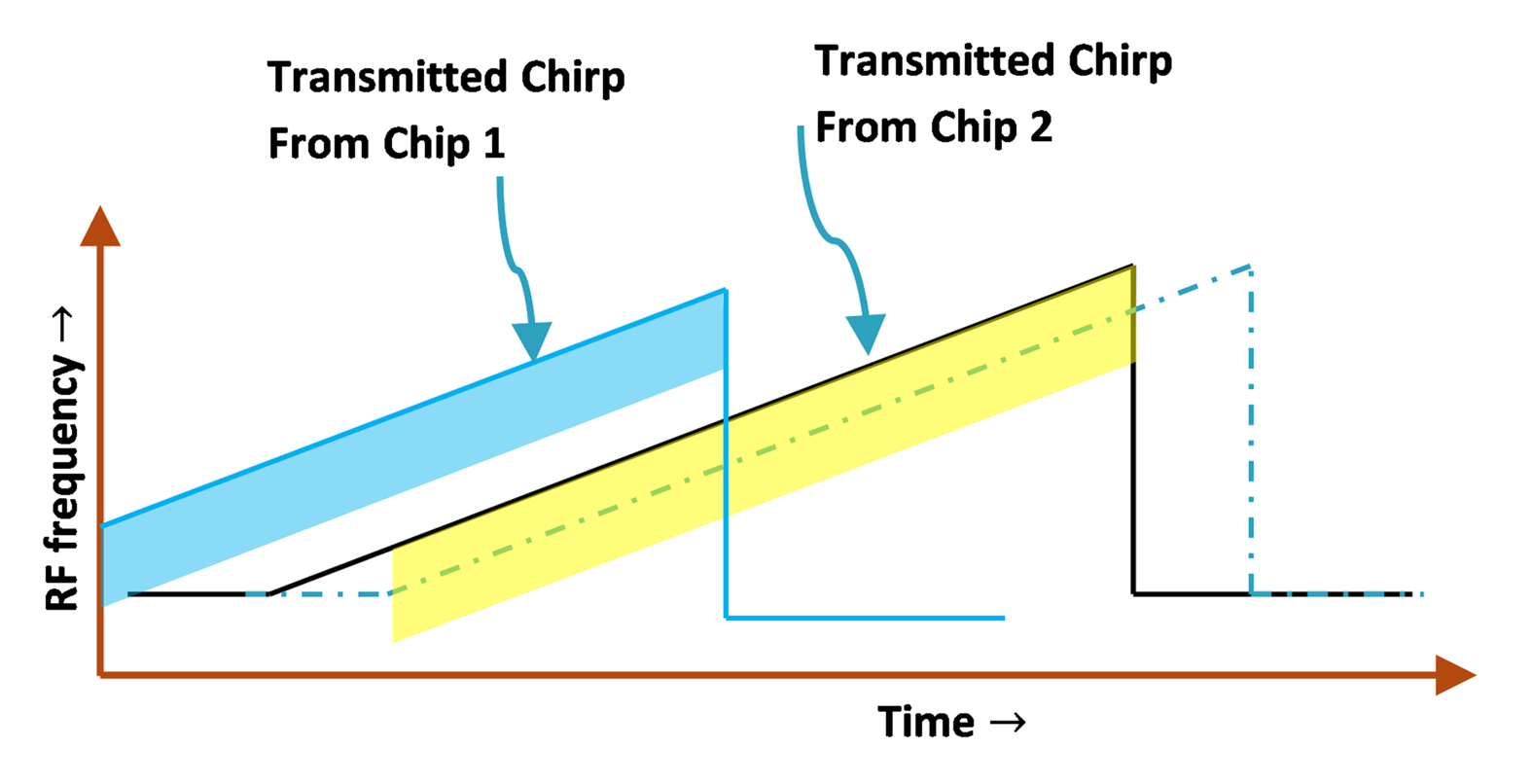
If a single manufacturer is building all the radars, they can be made so as to be synchronized to the same clock, to a global time for that particular factory. If every radar device is then configured with the same kind of chirp and frame, it can result in parallel interferers. However, if every radar's frame is offset, approximately one microsecond or so to the global times so that they do not interfere with other radars, then a large number of radars can coexist in a limited space and in the same bandwidth. For example, if the chirp time is 100 microseconds, and the max distance of interest is 150 meters; that is, the time of transmit is less than one microsecond then approximately 100 such radars can coexist in the same bandwidth. Synchronization also lets frames be stacked one after the other, so as not to interfere with other radars.
 Figure 3-2 Precise Intra-Chirp Time-Slot Planning
A simple method to achieve synchronization between radars that are placed close-by is through the master/slave mode in TI radar devices. In this scheme, one device is designated the master. This device generates triggers to the slave devices when it transmits a frame. The slaves can then delay, using this signal to trigger their own frames after a precisely defined delay.