SWRU467A February 2017 – June 2018 CC3120
-
CC3120 SimpleLink™ Wi-Fi® Internet-on-a chip™ Solution SDK Getting Started Guide
- Trademarks
- 1 Introduction
- 2 Prerequisites
- 3 Board Configuration
- 4 Programming the CC3120 BoosterPack™
- 5 Getting Started With the MSP-EXP432P401R LaunchPad™
- 6 Getting Started With SimpleLink™ Studio
- Revision History
4 Programming the CC3120 BoosterPack™
Regardless of the host MCU (MSP432 or Windows PC as SimpleLink Studio mode), the CC3120BOOST or BOOSTXL-CC3120MOD board must be programmed. As a minimum, the Service Pack is required. Other system and configuration files are also programmed by default.
To program a CC3120 BoosterPack, the CC31XXEMUBOOST board is required. Section 3.1 describes the setup.
To program a CC3120 BoosterPack, install the UniFlash utility and perform the following steps:
- Connect the CC31XXEMUBOOST board to the PC using the micro USB cable.
- Launch UniFlash, select CC3120/CC3220 device, and then click the Start Image Creator button (see Figure 10).
- Select the New Project button to enter the project information (see Figure 11).
- Enter a project name.
- Select CC3120 as the Device Type.
- Select Develop as the Device Mode (choose Production mode in final production).
- Click the Create Project button.
- Click the Connect button on the right side of the screen to connect to the board. If the connection is successful, the device information appears on the right side of the web page (see Figure 12).
- On the left side of the page, click the Service Pack tab to bring up the Service Pack File Name selection dialog.
- Click the Browse button and navigate to the Service Pack directory to select the binary (see Figure 13).
- Now click the Generate Image button
 on the right side of the web page to enter the programming page.
 - Click the center Program Image (Create & Program) button to create the image and start flashing it (see Figure 14). This operation may take a while to complete. Once the process is finished, a confirmation dialog appears.
- Once programming is complete, click the Disconnect button on the right side.
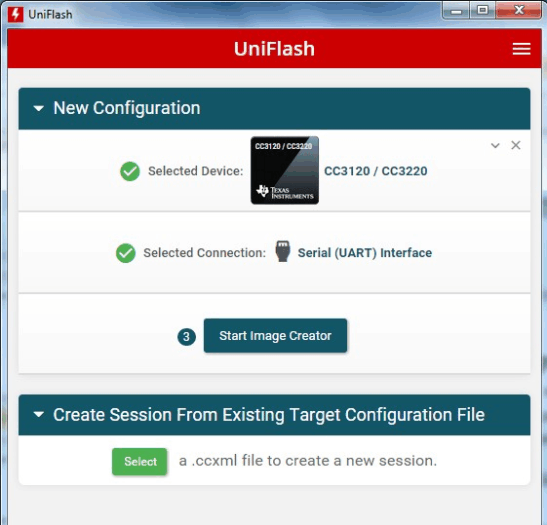 Figure 10. UniFlash Main Configuration Page
 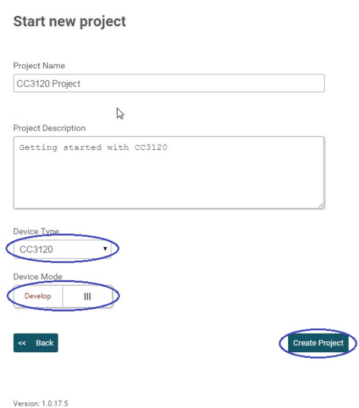 Figure 11. UniFlash Create Project
 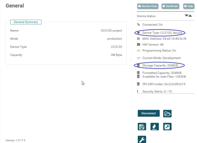 Figure 12. UniFlash Connect to CC3120
 The Service Pack is in the SDK under the <SDK install Dir>/tools/cc31xx_tools/servicepack-cc3x20 directory.
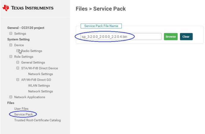 Figure 13. UniFlash Service Pack
 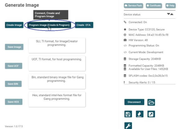 Figure 14. UniFlash Program Image