SWRU647 September 2026
- 1
- Description
- Features
- 1Evaluation Module Overview
-
2Hardware
- 2.1 AWRL6888EVM Antenna
- 2.2 EVM Mux Block Diagram
- 2.3 Switch Settings
- 2.4 Push Button Switches
- 2.5 LEDs
- 2.6 DC Input Jack
- 2.7 USB Connector
- 2.8 DCA1000 HD Connector
- 2.9 BoosterPack Connector for LaunchPad Connectivity
- 2.10 CAN-FD_A Connector
- 2.11 CAN-FD_B Connector
- 2.12 LIN-PHY Connector
- 2.13 I2C Connections
- 2.14 XDS110 Interface
- 2.15 FTDI Interface
- 2.16 DCA1000EVM Mode
- 2.17 PCB Storage and Handling Recommendations
- 3Software, Development Tools, and Example Code
- 4Hardware Design Files
- 5Additional Information
- 6References
2.4 Push Button Switches
Table 2-5 contains list of Push Button Switches on the AWRL6888EVM. The User switches are connected to GPIO and can be used for quick integration of a simple interface.
Table 2-4 List of Push Button Switches
| Switch Reference Designators | Usage | Comments | Image |
|---|---|---|---|
| S2 | Reset Switch | This Switch can be used to reset the AWRL6888 device |  |
| S3 | User Switch 1 | When pushed, GPIO_2 logic is pulled high | 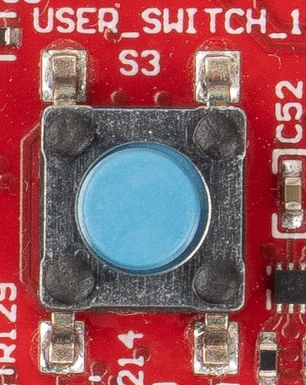 |
| S6 | User Switch 2 | When pushed, GPIO_6 logic is pulled high |  |