TIDT238 July   2021 TL7700-SEP


  1. 1Description
  2. 2Test Prerequisites
    1. 2.1 Voltage and Current Requirements
    2. 2.2 Considerations
    3. 2.3 Dimensions
  3. 3Testing and Results
    1. 3.1 Efficiency Graphs
    2. 3.2 Efficiency Data
    3. 3.3 Thermal Images
    4. 3.4 EMI
  4. 4Waveforms
    1. 4.1 Switching
    2. 4.2 Output Voltage Ripple
    3. 4.3 Load Transients
    4. 4.4 Start-up Sequence

Start-up Sequence

Start-up behavior is determined by the start-up resistors (R1 and R2) and VCC capacitor (C2).

The output goes up after 2 seconds with 100-kΩ start-up resistors and a 22-µF capacitor.
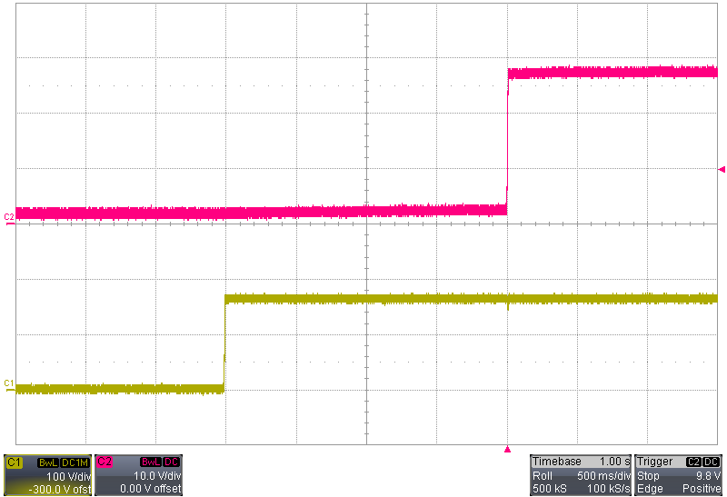
GUID-20210427-CA0I-3DBM-NJKC-Q8VCWF0WL67Z-low.pngFigure 4-4 Start-up