TIDUEZ4 May   2021


  1.   Description
  2.   Resources
  3.   Features
  4.   Applications
  5.   5
  6. 1System Description
  7. 2System Overview
    1. 2.1 Block Diagram
    2. 2.2 Highlighted Products
      1. 2.2.1 SimpleLink MCU
        1. 2.2.1.1 CC3235MODS
        2. 2.2.1.2 CC1352R LaunchPad
          1. 2.2.1.2.1 CC1352R
      2. 2.2.2 Power
        1. 2.2.2.1 TPS63802
        2. 2.2.2.2 TPS63900
        3. 2.2.2.3 TPS62825
        4. 2.2.2.4 TPS7A03
        5. 2.2.2.5 TPS7A20
        6. 2.2.2.6 TPS62840
        7. 2.2.2.7 TPS22919
        8. 2.2.2.8 LM66100
      3. 2.2.3 Peripherals
        1. 2.2.3.1 OPT3004
        2. 2.2.3.2 DRV8837C
        3. 2.2.3.3 TPA2011
        4. 2.2.3.4 TLV61048
      4. 2.2.4 OmniVision Video Encoder OA7000
      5. 2.2.5 OmniVision Image Sensor SP2329
      6. 2.2.6 YTOT Lens Module
    3. 2.3 Design Considerations
      1. 2.3.1  Input Power: Battery and USB
      2. 2.3.2  Power Requirements
      3. 2.3.3  Camera Wake-up and Day or Night Sensing
        1. 2.3.3.1 PIR and MSP430 Based Motion Detection Design for Low Cost and High Performance
      4. 2.3.4  Battery Gauging
      5. 2.3.5  IR LED Illumination
      6. 2.3.6  IR Cut Filter
      7. 2.3.7  Audio
      8. 2.3.8  System Operation
      9. 2.3.9  Wi-Fi and Host Subsystem
      10. 2.3.10 Firmware Control
        1. 2.3.10.1 Application Flow
  8. 3Hardware, Software, Testing Requirements, and Test Results
    1. 3.1 Hardware
    2. 3.2 Software
    3. 3.3 Setup
      1. 3.3.1 Configuration Steps for Video over Wi-Fi
      2. 3.3.2 (Optional) Flash OA7000 With Latest Firmware or Stream Video Over USB
      3. 3.3.3 Audio Streaming
      4. 3.3.4 LPSTK-CC1352R Configuration Steps for Camera Module
    4. 3.4 Test Results
      1. 3.4.1 Power Supply Rails and Current Consumption
      2. 3.4.2 Battery Life Calculations
      3. 3.4.3 Video Streaming
      4. 3.4.4 IR LED Drive
  9. 4Design and Documentation Support
    1. 4.1 Design Files
      1. 4.1.1 Schematics
      2. 4.1.2 Bill of Materials
    2. 4.2 Software
    3. 4.3 Support Resources
    4. 4.4 References
    5. 4.5 Trademarks
  10. 5About the Author

Setup

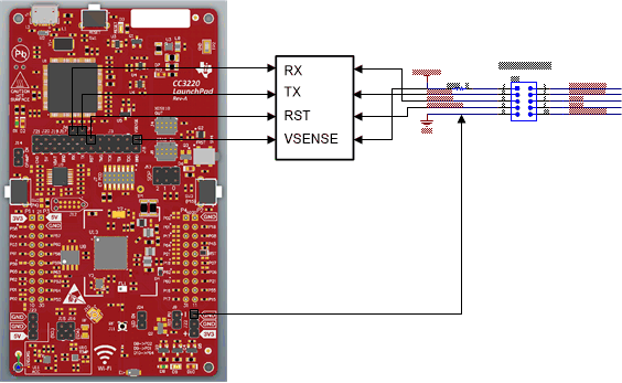
The following connections are required for programming (or updating) the software for the wireless camera module:

  • Connections between CC32xx LaunchPad and wireless camera module (see Figure 3-2):
    • UART TX
    • UART RX
    • GND
    • Reset
    • VSENSE (Level shifter voltage)
Note: Unmount the headers as shown in Figure 3-1.
GUID-20210422-CA0I-PMDG-ML6N-8LQPHDQHKBH1-low.jpg Figure 3-1 Jumper Setting on CC32xx
GUID-20210422-CA0I-6FZ9-64GJ-R22VRD07PKVM-low.gif Figure 3-2 Connections Between CC32xx LaunchPadâ„¢ and Wireless Camera Module (J13 Connector)
  • Reset Connection: For proper operation of the OA7000, the Wi-Fi device should be able to reset it. To do so, HOST_ON pin (pin 8, J7 connector) of the camera module is connected to the NWP debug pin (pin 2, J13 connector) as shown in Figure 3-3.
GUID-20210422-CA0I-PSF9-FJSG-2GGBKVK4ZRGN-low.gif Figure 3-3 Reset Connection
  • Optional connections required for debug over JTAG
    • JTAG (JTAG connector from LaunchPad connected to the J5 connector of the camera module as shown in Figure 3-4)
    • nRESET
    • GND
GUID-20210422-CA0I-F7PM-ZHHP-WGNCMKFMQ5NS-low.gif Figure 3-4 JTAG Connection
  • Mount the sensor board on the video processor board. Power up the camera using the battery connector (J1) or using a micro-B USB as shown in Figure 3-5.
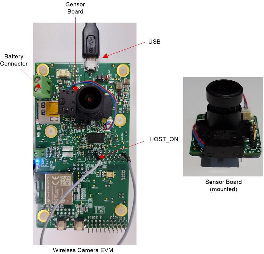
GUID-20210422-CA0I-5GRK-V2KS-0HLWDR750HZN-low.jpg Figure 3-5 Wireless Camera Module With Sensor Board Mounted