TIDUF51 November 2023
- 1
- Description
- Resources
- Features
- Applications
- 6
- 1System Description
- 2System Overview
- 3Hardware, Software, Testing Requirements, and Test Results
- 4Design and Documentation Support
- 5About the Author
2.3.1 IWRL6432
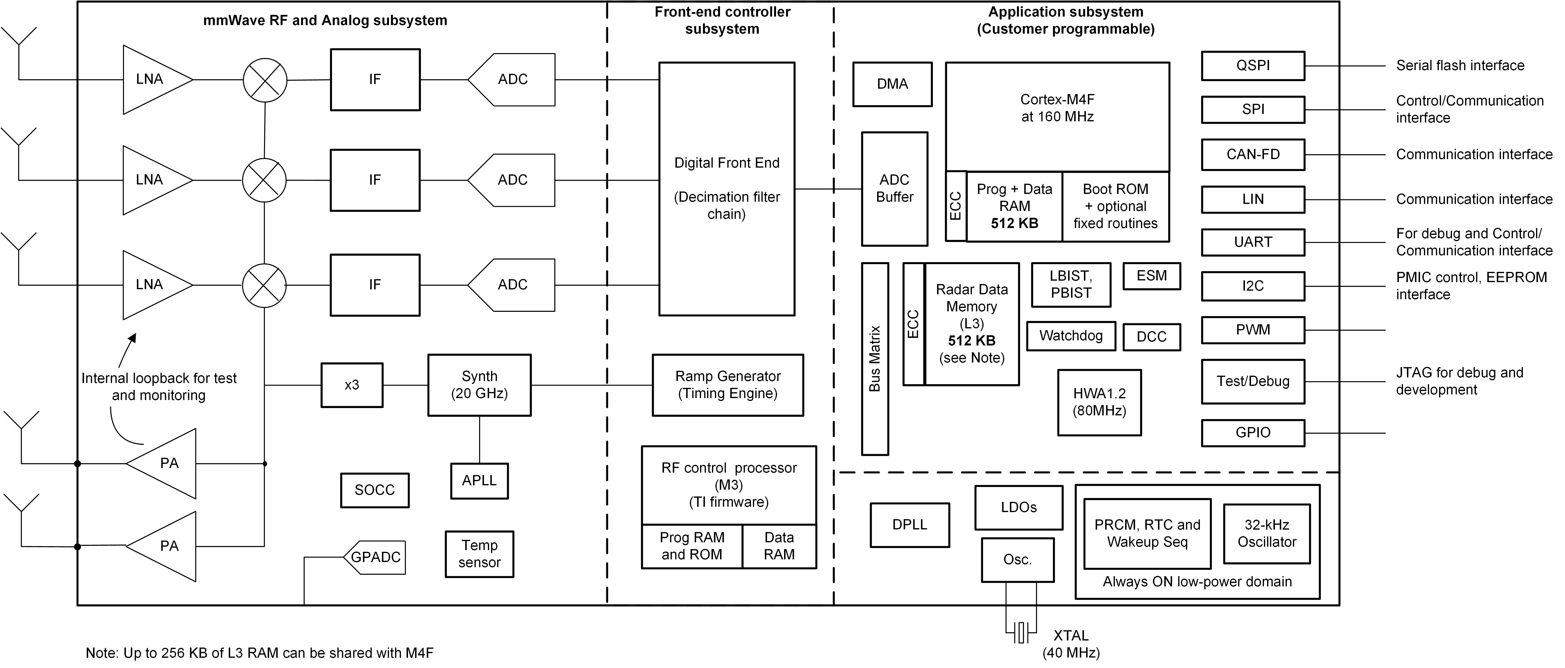
The IWRL6432 mmWave sensor device is an integrated single-chip mmWave sensor based on Frequency Modulated Continuous Wave (FMCW) radar technology. The device is capable of operation in the 57-GHz to 64-GHz band and is partitioned into mainly four power domains:
RF, Analog Sub-System: This block includes all the RF and Analog components required to transmit and receive the RF signals.
Front-End Controller Sub-System (FECSS): FECSS contains the processor responsible for radar front-end configuration, control, and calibration.
Application Sub-System (APPSS): APPSS is where the device implements a user-programmable Arm® Cortex® M4 allowing for custom control and automotive interface applications. Top Sub-System (TOPSS) is part of the APPSS power domain and contains the clocking and power management subblocks.
Hardware Accelerator (HWA): HWA block supplements the APPSS by offloading common radar processing such as fast Fourier transform (FFT), Constant False Alarm rate (CFAR), scaling, and compression.

Figure 2-8 IWRL6432 Block Diagram
The IWRL6432 device is specifically designed to have separate knobs for each of the above-mentioned power domains to control their states (power ON or OFF) based on use-case requirements. The device also features the capability to exercise various low-power states like sleep and deep sleep, where low-power sleep mode is achieved by clock gating and by turning off the internal IP blocks of the device. The device also provides the option of keeping some contents of the device, like the application image or RF profile retained in such scenarios.
Additionally, the device is built with TI’s low-power, 45-nm radio-frequency (RF) complementary MOS (CMOS) process and enables unprecedented levels of integration in an extremely small form factor. IWRL6432 is designed for low-power, self-monitored, ultra-accurate radar systems in the industrial (and personal electronics) space for applications such as building and factory automation, commercial and residential security, personal electronics, presence and motion detection, and gesture detection and recognition for human machine interfaces.