TIDUF51 November   2023


  1.   1
  2.   Description
  3.   Resources
  4.   Features
  5.   Applications
  6.   6
  7. 1System Description
    1. 1.1 Key System Specifications
  8. 2System Overview
    1. 2.1 Block Diagram
    2. 2.2 Design Considerations
      1. 2.2.1 mmWave Sensor Application
      2. 2.2.2 IWR6432 UART Communication
      3. 2.2.3 LAUNCHXLCC1352R1 Communication
      4. 2.2.4 Sensors Application
      5. 2.2.5 Power Supply Design
      6. 2.2.6 IWRL6432 Power Supply Considerations
    3. 2.3 Highlighted Products
      1. 2.3.1 IWRL6432
      2. 2.3.2 CC1352R
      3. 2.3.3 BQ25616
      4. 2.3.4 TPS62850
      5. 2.3.5 HDC3020
      6. 2.3.6 OPT3005
      7. 2.3.7 DRV5032
  9. 3Hardware, Software, Testing Requirements, and Test Results
    1. 3.1 Hardware Requirements
      1. 3.1.1 Getting Started Hardware
        1. 3.1.1.1 IWRL6432FSPEVM Initialization: IWRL6432 Programming
        2. 3.1.1.2 Base Board Initialization: CC1352R Programming
    2. 3.2 Software Requirements
    3. 3.3 Test Setup
      1. 3.3.1 Demonstration Setup
    4. 3.4 Test Results
      1. 3.4.1 Radar Detect Distance Measurement
      2. 3.4.2 People Counting Test Results
      3. 3.4.3 Wireless Range Test Results
      4. 3.4.4 Power Consumption Test Results
  10. 4Design and Documentation Support
    1. 4.1 Design Files
      1. 4.1.1 Schematics
      2. 4.1.2 BOM
      3. 4.1.3 PCB Layout Recommendations
        1. 4.1.3.1 Layout Prints
      4. 4.1.4 Altium Project
      5. 4.1.5 Gerber Files
      6. 4.1.6 Assembly Drawings
    2. 4.2 Tools and Software
    3. 4.3 Documentation Support
    4. 4.4 Support Resources
    5. 4.5 Trademarks
  11. 5About the Author

Demonstration Setup

Use the following setup procedures for the demonstration:

  1. Clamp the base board and IWRL6432FSPEVM on a tripod. The height is 1.9-m high from the ground, and there is no downward tilt: 0 degree.
  2. Power up the base board and IWRL6432FSPEVM with an 18650 Li-ion battery.
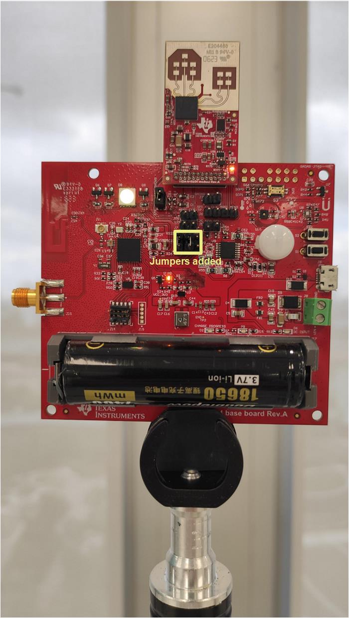
    GUID-20231102-SS0I-WXWQ-TXTW-RFCM3DNVNFPD-low.jpg Figure 3-10 Base Board and IWRL6432FSPEVM on a Tripod
  3. Use a USB cable to power up and connect the LAUNCHXLCC1352R1 wireless MCU LaunchPad™ to a PC.
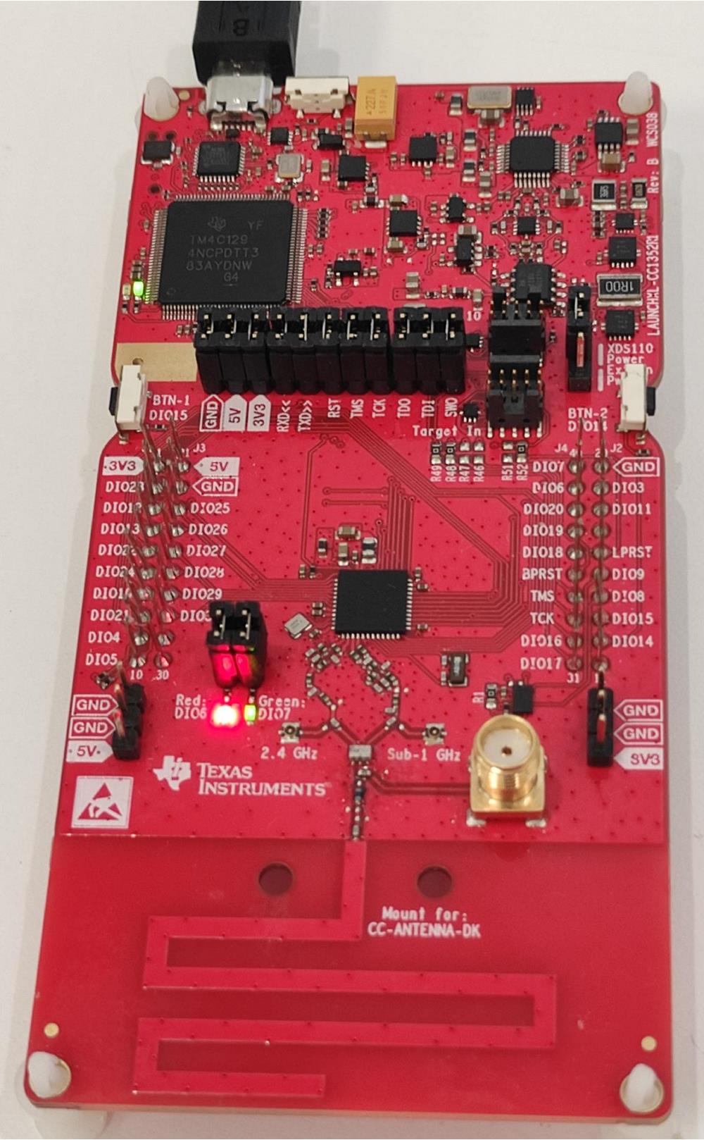
    GUID-20231102-SS0I-S4LT-8GGR-NP0TTBP2PR32-low.jpg Figure 3-11 LAUNCHXLCC1352R1 Connected to a PC
  4. Position the LAUNCHXLCC1352R1 less than 1 m from the base board and IWRL6432FSPEVM.
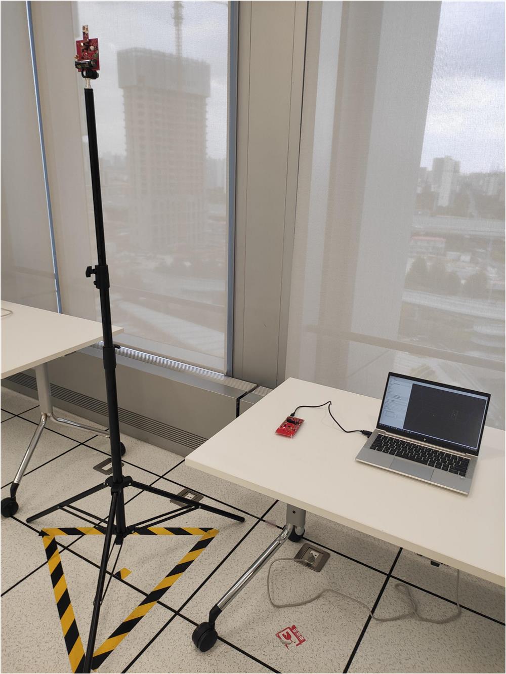
    GUID-20231102-SS0I-48KW-XXHV-GH4MRLGMQR8N-low.jpg Figure 3-12 Demonstration Position Setup
  5. Run the GUI software on a PC and start the demonstration. Click the button with the 3 steps shown in Figure 3-13. See the GUI configuration file in step 2 at TIDA-010254.
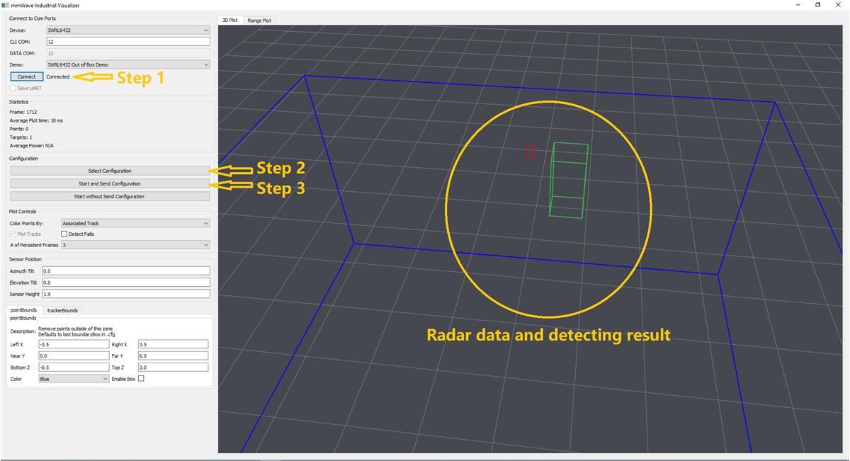
    GUID-20231101-SS0I-KQD4-HNH1-DBZXZKNXV7NG-low.png Figure 3-13 GUI Software for Demonstration