TIDUF51 November 2023
- 1
- Description
- Resources
- Features
- Applications
- 6
- 1System Description
- 2System Overview
- 3Hardware, Software, Testing Requirements, and Test Results
- 4Design and Documentation Support
- 5About the Author
3.1.1.1 IWRL6432FSPEVM Initialization: IWRL6432 Programming
Complete the following steps to initialize the IWRL6432FSPEVM:
- Connect the IWRL6432FSPEVM to the receptacle connector on the base board (J1).
- Select IWRL6432 Sense-on-Power (SOP) mode, by
using S3 on the base board. Table 3-1 provides a description of the SOP modes. A "0" represents pulling the pin low
and a "1" represents pulling the pin high. The switch S3 position "off"
represents "0" and "on" represents "1".Table 3-1 SOP Mode
MODE SOP0 SOP1 MODE DESCRIPTION 1 0 0 Flashing mode: IWRL6432 flashes the user application to QSPI flash 2 1 0 Functional mode: IWRL6432 loads the user application from QSPI flash to the internal RAM and runs application from RAM. - Set the SOP mode to
flashing mode, as Figure 3-1 shows.Figure 3-6 illustrates using a LaunchPad and removing the XDS jumpers.
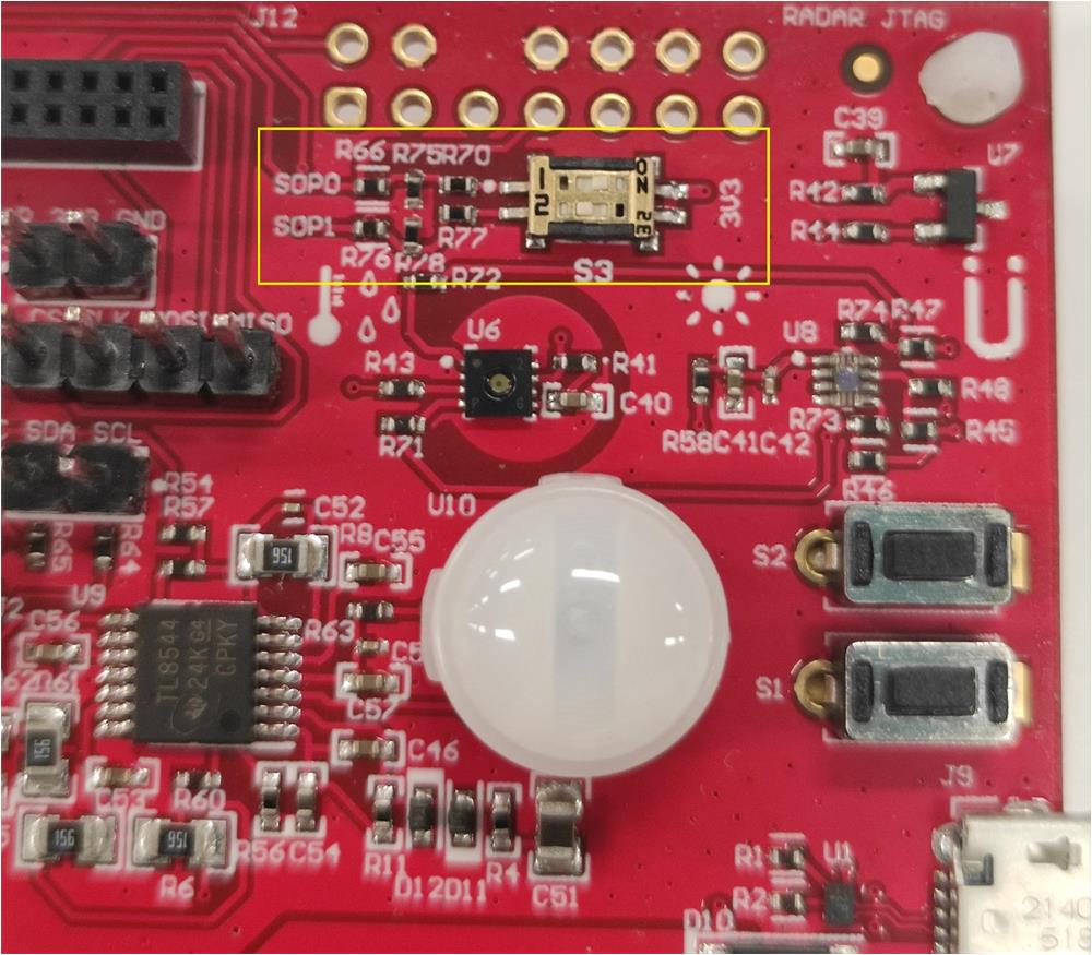 Figure 3-1 Setting the SOP to
Flashing Mode
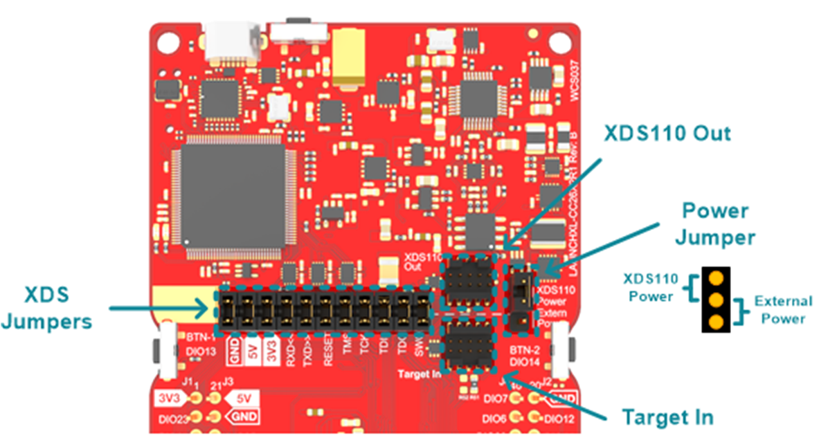 Figure 3-2 Removing XDS
Jumpers
 - Use jumper wires to
connect the IWRL6432 UART port on the base board to the LaunchPad XDS110 UART
pins of the debugger.
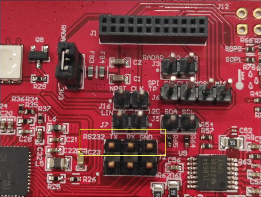 Figure 3-3 IWRL6432 UART Port on
the Base Board
 - Use an 18650 Li-ion battery, 5-V USB, or external
DC power to power the base board and IWRL6432FSPEVM.
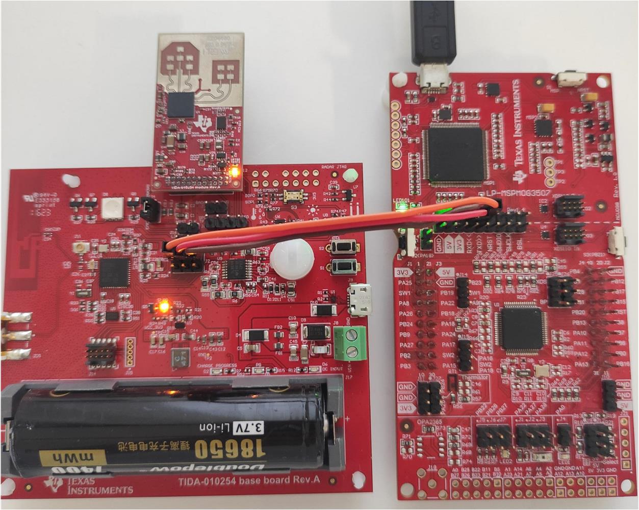 Figure 3-4 IWRL6432 Hardware
Setup for Programming
The IWRL6432 is ready for programming.
TI provides a mmWave Software Development Kit (SDK) to flash a binary file to IWRL6432. See the MMWAVE-L-SDK tool page to get this SDK.
The UNIFLASH software can also be used to flash the IWRL6432.
Use the following steps to flash the IWRL6432:
- Open the UniFlash software
- Select mmWave from the Category header
- Select IWRL6432 from the field of available devices
- Click the Start button.
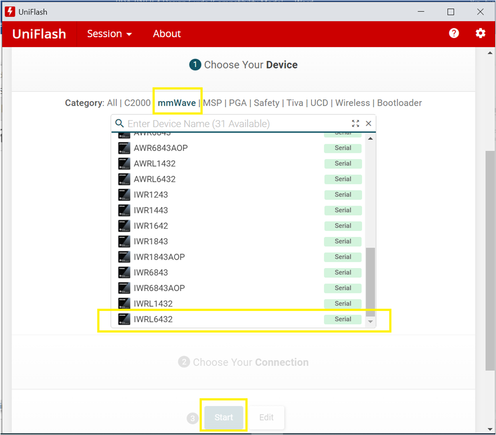 Figure 3-5 UniFlash Software
Configuration for IWRL6432
Figure 3-5 UniFlash Software
Configuration for IWRL6432After the IWRL6432 programming completes, remove the jumper wires on the IWRL6432 UART port (J2) on the base board, and set the SOP mode to functional mode using the switch S3.