SBFS042 June 2020 AFE3010
PRODUCTION DATA.
- 1 Features
- 2 Applications
- 3 Description
- 4 Revision History
- 5 Pin Configuration and Functions
- 6 Specifications
- 7 Detailed Description
- 8 Application and Implementation
- 9 Power Supply Recommendations
- 10Layout
- 11Device and Documentation Support
- 12Mechanical, Packaging, and Orderable Information
Package Options
Mechanical Data (Package|Pins)
- RGT|16
Thermal pad, mechanical data (Package|Pins)
- RGT|16
Orderable Information
7.3.7.2 Continuous Self-Test
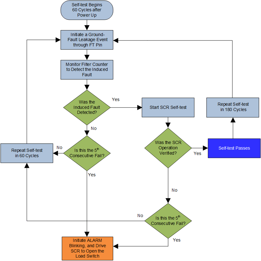
The AFE3010 performs the following continuous mode self-tests. If any of these tests fail, the device does not wait to perform another self-test. Rather, the AFE3010 immediately fires the SCR and sets the ALARM blinking as 1-s intervals (for 60-Hz systems).
- Open Solenoid Test: The AFE3010 checks for transition of AC line signal at the PH and SCR_TST pins. If the device does not detect a transition of the line signal at PH or SCR_TST pins for approximately 100 ms, then the device reads a self-test fail.
- Diode Bridge Test: if a diode is shorted in the diode bridge rectifier, the device is able to detect the variation in supply current from the diode bridge. This detection is considered a self-test fail, and the AFE3010 fires the SCR and sets the ALARM blinking at 1-s intervals (for 60-Hz systems).
- Amplifier Short/ Open: The device monitors for sustained fault current conditions, even after the fault current has been detected and SCR has fired. The primary purpose of this self-test is to detect a single-point failure with the amplifier signal pins and associated components. If a failure is detected, the device fires SCR one more time and LED starts blinking. In the event the load switch doesn't open after SCR is fired, this self-test recognizes a failure and starts the LED blinking.
 Figure 10. AFE3010 Self-test Sequence