JAJSAR0B March   2007  – October 2017 LM95214

PRODUCTION DATA.  

  1. 特長
  2. アプリケーション
  3. 概要
    1.     リモート1温度エラー、TA=TD
  4. 改訂履歴
  5. 概要(続き)
  6. Pin Configuration and Functions
    1.     Pin Functions
  7. Specifications
    1. 7.1 Absolute Maximum Ratings
    2. 7.2 ESD Ratings
    3. 7.3 Recommended Operating Conditions
    4. 7.4 Thermal Information
    5. 7.5 Electrical Characteristics: Temperature-to-Digital Converter
    6. 7.6 Logic Electrical Characteristics: Digital DC Characteristics
    7. 7.7 Switching Characteristics: SMBus Digital
    8. 7.8 Typical Characteristics
  8. Detailed Description
    1. 8.1 Overview
    2. 8.2 Functional Block Diagram
    3. 8.3 Feature Description
      1. 8.3.1 Conversion Sequence
      2. 8.3.2 Power-On-Default States
      3. 8.3.3 SMBus Interface
      4. 8.3.4 Temperature Conversion Sequence
        1. 8.3.4.1 Digital Filter
      5. 8.3.5 Fault Queue
      6. 8.3.6 Temperature Data Format
      7. 8.3.7 SMBDAT Open-Drain Output
      8. 8.3.8 TCRIT1, TCRIT2, and TCRIT3 Outputs
      9. 8.3.9 TCRIT Limits and TCRIT Outputs
    4. 8.4 Device Functional Modes
      1. 8.4.1 Diode Fault Detection
      2. 8.4.2 Communicating With the LM95214
      3. 8.4.3 Serial Interface Reset
      4. 8.4.4 One-Shot Conversion
    5. 8.5 Register Maps
      1. 8.5.1 LM95214 Registers
        1. 8.5.1.1 Value Registers
          1. 8.5.1.1.1 Local Value Registers
          2. 8.5.1.1.2 Remote Temperature Value Registers With Signed Format
          3. 8.5.1.1.3 Remote Temperature Value Registers With Unsigned Format
        2. 8.5.1.2 Diode Configuration Register
          1. 8.5.1.2.1 Remote 1-4 Offset
        3. 8.5.1.3 Configuration Registers
          1. 8.5.1.3.1 Main Configuration Register
          2. 8.5.1.3.2 Conversion Rate Register
          3. 8.5.1.3.3 Channel Conversion Enable
          4. 8.5.1.3.4 Filter Setting
          5. 8.5.1.3.5 1-Shot
        4. 8.5.1.4 Status Registers
          1. 8.5.1.4.1 Common Status Register
          2. 8.5.1.4.2 Status 1 Register (Diode Fault)
          3. 8.5.1.4.3 Status 2 (TCRIT1)
          4. 8.5.1.4.4 Status 3 (TCRIT2)
          5. 8.5.1.4.5 Status 4 (TCRIT3)
        5. 8.5.1.5 Mask Registers
          1. 8.5.1.5.1 TCRIT1 Mask Register
          2. 8.5.1.5.2 TCRIT2 Mask Registers
          3. 8.5.1.5.3 TCRIT3 Mask Register
        6. 8.5.1.6 Limit Registers
          1. 8.5.1.6.1 Local Limit Register
          2. 8.5.1.6.2 Remote Limit Registers
          3. 8.5.1.6.3 Common Tcrit Hysteresis Register
        7. 8.5.1.7 Identification Registers
  9. Application and Implementation
    1. 9.1 Application Information
    2. 9.2 Typical Application
      1. 9.2.1 Design Requirements
    3. 9.3 Diode Non-Ideality
      1. 9.3.1 Diode Non-Ideality Factor Effect on Accuracy
      2. 9.3.2 Calculating Total System Accuracy
      3. 9.3.3 Compensating for Different Non-Ideality
  10. 10Power Supply Recommendations
  11. 11Layout
    1. 11.1 Layout Guidelines
    2. 11.2 Layout Example
  12. 12デバイスおよびドキュメントのサポート
    1. 12.1 ドキュメントの更新通知を受け取る方法
    2. 12.2 コミュニティ・リソース
    3. 12.3 商標
    4. 12.4 静電気放電に関する注意事項
    5. 12.5 Glossary
  13. 13メカニカル、パッケージ、および注文情報

パッケージ・オプション

メカニカル・データ(パッケージ|ピン)
サーマルパッド・メカニカル・データ
発注情報

Conversion Sequence

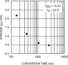
The LM95214 takes approximately 190 ms to convert the Local Temperature, Remote Temperatures 1 through 4, and to update all of its registers. These conversions for each thermal diode are addressed in a round robin sequence. Only during the conversion process the busy bit (D7) in Status register (02h) is high. The conversion rate may be modified by the Conversion Rate bits found in the Configuration Register (03h). When the conversion rate is modified a delay is inserted between each round of conversions, the actual time for each round remains at 190 ms (typical all channels enabled). The time a round takes depends on the number of channels that are on. Different conversion rates will cause the LM95214 to draw different amounts of average supply current as shown in Figure 10. This curve assumes all the channels are on. If channels are turned off the average current will drop because the round robin time will decrease and the shutdown time will increase during each conversion interval.
LM95214 30006106.gifFigure 10. Conversion Rate Effect on Power Supply Current