SBAA449B October 2020 – October 2021 TMAG5110 , TMAG5110-Q1 , TMAG5111 , TMAG5111-Q1
3.1.1 Pole Count
Pole count of the magnet will impact the minimum resolution of angular measurements. For instance, in a basic cylinder magnet with diametric polarization only two discrete positions for each sensor can be determined. Because of the phase differences, we can determine angular position to 90°. As the pole count of the magnet increases our angular step size improves. This change in resolution will also help scale the expected angle error that results from amplitude or sensitivity mismatch.
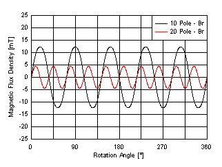
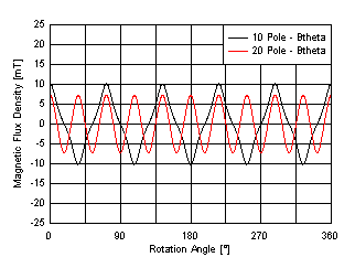
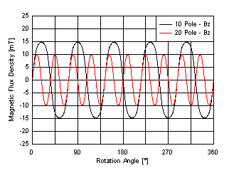
There is a trade off when increasing pole count. Magnetic flux density, or B-Field, in each direction will weaken as the pole count increases. Therefore, a given sensor needs to be closer to the magnet or have greater sensitivity to detect each pole transition. Figure 3-2 to Figure 3-4 illustrate the simulation results of the B-Field produced by a magnetic ring with 10 poles and another with 20 poles. Here the sensor is no longer in plane with the magnet, but has been displaced downward 1.5 mm beneath the outer edge. We observe in this location that Bz is the dominant component of the B-Field vector with a peak value of about 10 mT in the 20 pole case.
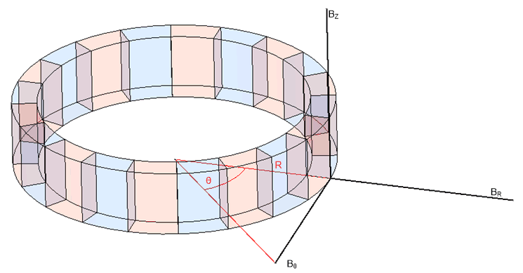
In the simulation examples, it is informative to use cylindrical coordinates rather than Cartesian. As a result, instead of representing the output vectors in terms of X, Y, and Z, the plots have coordinates relative to R (directed radially outward from the z-axis), θ (directed tangentially with respect to a point at radius R), and Z. This ensures that no matter where the sensor is placed with respect to the magnet that we can correctly extract the appropriate vectors as we explore the space surrounding the magnet.
 Figure 3-1 Cylindrical Coordinate
System
Figure 3-1 Cylindrical Coordinate
SystemEach magnet shares identical dimensions, material properties, and sensor placement. The only difference is the number of poles. Notice the drop in measurable magnetic field as a result of increasing the number of poles. Also, notice that the sinusoidal shape present in the θ component of the 20-pole version becomes more triangular for the 10 pole magnet. A more sinusoidal response is expected here with a larger air gap, but this comes at the cost of reduced amplitude.
A higher pole count magnet provides better angular resolution, but also results in a weaker magnetic field. The measured magnetic flux density must be large enough in both measured axes to properly detect quadrature.
 Figure 3-2 Impact of Pole Count - Br
 Figure 3-3 Impact of Pole Count - Bθ
 Figure 3-4 Impact of Pole Count - Bz