SBAA449B October 2020 – October 2021 TMAG5110 , TMAG5110-Q1 , TMAG5111 , TMAG5111-Q1
3.2.2.1 On-Axis Magnetic Field
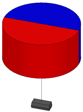
Unlike all of the other scenarios shown in this document, an On-Axis measurement is best suited when using a diametric magnet with only a single pole pair. The sensor should be placed beneath the magnet along the axis of rotation for this type of alignment.
 Figure 3-18 On Axis
Alignment
Figure 3-18 On Axis
AlignmentIn this position, the magnetic field will always be directed parallel to the magnet face as it rotates, and will therefore produce no z-component.
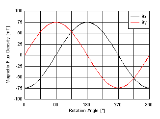
For this example, we will deviate from the 20-pole bonded ceramic magnet and show the response from a 24.5-mm diameter disc magnet with a thickness of 12.25 mm. The sensor is placed approximately 10 mm below the magnet. Notice that the magnetic flux density for each component has a peak of 75 mT. It would certainly be possible for TMAG5110 or TMAG5111 to operate in this system with a smaller magnet or at a further distance.
What is noteworthy here is that the two components are perfectly 90° out of phase, and share the same peak amplitude. Alignment for this case is fairly simple, with a minimal impact due to amplitude differences.
 Figure 3-19 On-Axis Magnetic Field Components
The drawback for this type of magnet and alignment is resolution. We can only determine each 90° step. To get finer resolution with this type of magnet, the magnet needs to be geared to rotate at a higher ratio than the main body being sensed.
While we would only observe quadrature error to result from sensitivity mismatch, we still expect as much as 1.16° error with the worst case matching. Despite the input having a significantly larger magnitude than in the multi-pole case, the error is still greater than 1° due to the mechanical and electrical phase having a 1:1 ratio. When using a multi-pole magnet the angular resolution improves and will scale the error down.