SBAA449B October 2020 – October 2021 TMAG5110 , TMAG5110-Q1 , TMAG5111 , TMAG5111-Q1
1 Introduction
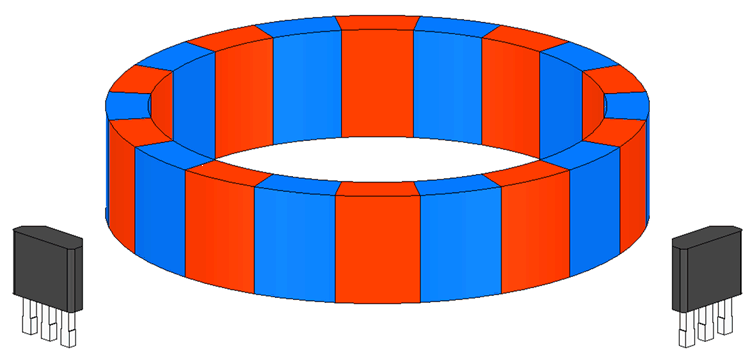
Quadrature detection of rotating magnetic fields is normally achieved using a dipole magnet by spacing two Hall-effect magnetic sensors 90° apart adjacent to the magnet. When using multi-pole magnets, this spacing may be set to any integer + ½ number of the pole spacing interval. Typically these magnets are polarized radially outward from the center of the ring, but there are also options to orient the polarization axially (vertically in the z-direction).
 Figure 1-1 Quadrature Placement for Two Sensors
Quadrature detection in rotary encoders allows the user to monitor speed and direction of rotation as well as incremental changes in angle. Multi-pole magnets improve resolution of these angle measurements. As the number of poles increases we can resolve smaller changes in angle.
There are a few challenges that must be overcome to develop a robust quadrature solution. Here the design requires the placement of each sensor such that each detects the exact same portion of the magnetic field as the magnet rotates. Placement and alignment errors, magnet tilt, and off axis magnet rotation may all contribute to measurement error. A detailed description of these factors is available in Using Hall Effect Position Sensors for Rotary Encoding Applications.
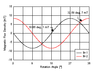
Additionally, variations in device sensitivity will impact overall quadrature accuracy. For instance, let us consider a device with a typical BOP point of 4 mT with ±3 mT of tolerance. We must suppose the worst case where one sensor might trigger at 1 mT and the other will trigger at 7 mT. With each sensor in plane to a 20-pole Neobond12M magnet and each perfectly placed at a distance of 3.25 mm, we monitor a magnetic flux density plot as shown in Figure 1-2. The magnet has an outer diameter of 25.5 mm and an inner diameter of 21.5 mm. Unless otherwise noted, we will use this magnet throughout this discussion.
The magnetic flux density observed by each sensor is identical, but is electrically out of phase by 90° due to placement. With 20-pole magnet, each pole pair occupies 36° and will define one full period at the input. Therefore, 90° electrical phase separation is equivalent to 9° of mechanical rotation. The field component in the direction radially outward from the edge of the magnet reaches a peak amplitude of just over 8 mT, which is sufficient to always tigger both devices. If we consider the unlikely scenario of the worst-case device sensitivities, there is a possibility for a maximum 4.9° of mechanical error due to sensitivity mismatch. This error results from the mismatch between the expected phase offset and the observed phase produced when the extreme BOP thresholds occur in the same system.
 Figure 1-2 Two-Sensor Quadrature
Using a 2D sensor such as TMAG5110 or TMAG5111 can help simplify the design and reduce build constraints. Placing both sensors internal to a single package immediately helps reduce potential alignment offsets. Additionally, the accuracy of TMAG5110 sensor is also improved. TMAG5110 combines two sensors oriented orthogonally to each other into a single package with an operating point symmetry of 1.5 mT.
We should now consider both the field directed in the z-direction and the field directed tangential (θ) to the face of the magnet.
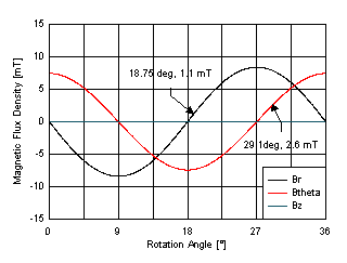
 Figure 1-3 B-Field Components
In Figure 1-3, the 2D sensor is in the same relative position as before. We can see that the Z-component at this location is zero, so this requires a device sensitive to XY field components (Br and Bθ). With TMAG5110 or TMAG5111 , a through-hole package type is not required to achieve this alignment as XY, ZY, and ZX options are all available in the surface mount packaging.
Here, the tangential component (Bθ) has nearly the same amplitude as the radial component (Br). There is a slight variation in amplitude which will be additive to the error resulting from variation in device sensitivity. A 9° phase difference is expected between the two fields for this magnet. By adding the maximum BOP error between sensors, the resulting error is about 1.35°. This is a significant improvement on the previous scenario.
While this improvement is good, it could be improved further by carefully considering the nature of the magnetic field of a magnet and how it relates to our sensor placement.