SBAA449B October   2020  – October 2021 TMAG5110 , TMAG5110-Q1 , TMAG5111 , TMAG5111-Q1


  1.   Trademarks
  2. 1Introduction
  3. 2Latch Response of the 2D Hall Effect
  4. 3Two Axis Sensor Consideration
    1. 3.1 Magnet Selection
      1. 3.1.1 Pole Count
      2. 3.1.2 Magnet Strength
    2. 3.2 Sensor Selection
      1. 3.2.1 Axes of Sensitivity
        1. 3.2.1.1 In-Plane Sensor Alignment
        2. 3.2.1.2 Out-Of Plane Sensor Alignment
      2. 3.2.2 Sensor Placement
        1. 3.2.2.1 On-Axis Magnetic Field
        2. 3.2.2.2 In-Plane Magnetic Field
        3. 3.2.2.3 Out-of-Plane Magnetic Field
      3. 3.2.3 Sensitivity Selection
  5. 4Optimizing for Accuracy
    1. 4.1 Optimizing Placement for Accuracy
    2. 4.2 Optimizing a Magnet for Accuracy
  6. 5Application Implementation
  7. 6Summary
  8. 7References
  9. 8Revision History

In-Plane Magnetic Field

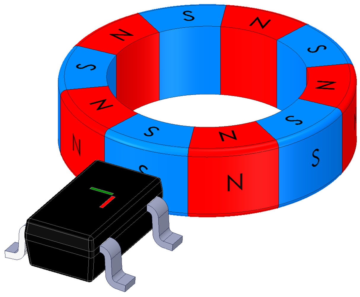
Figure 3-20 shows in-plane placement. Instead of using two separate devices to detect quadrature, we have a single 2D sensor coplanar to the magnet.
GUID-ED4408D2-4209-4005-AF1A-F6263E0EA0E7-low.pngFigure 3-20 Sensor In-Plane.

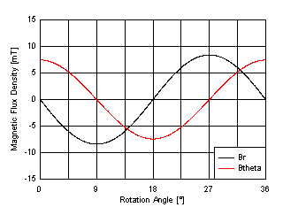
The radial component of the magnetic field is about the same amplitude here as it was beneath the magnet with a smaller air gap. When placed with a 3.25 mm spacing between the sensor and the magnet face we notice that the peak amplitudes between the two relevant components are quite similar, and there is no z-component.
GUID-20210108-CA0I-D6QS-LSCM-ZRCKTRNHJ34D-low.gifFigure 3-21 In-Plane Magnetic Field Components
In this alignment it is possible to achieve greater distances from the magnet. However, many systems may be mechanically prohibitive to using this approach. As shown in the Introduction, we can expect about 1.35° error due to amplitude mismatch and sensitivity error combined. If the magnet were placed closer to the sensor, this error would be expected to decrease.