SBOA571 august 2023 OPA2387 , OPA387 , OPA4387
3.1 First Order Shelving Filter
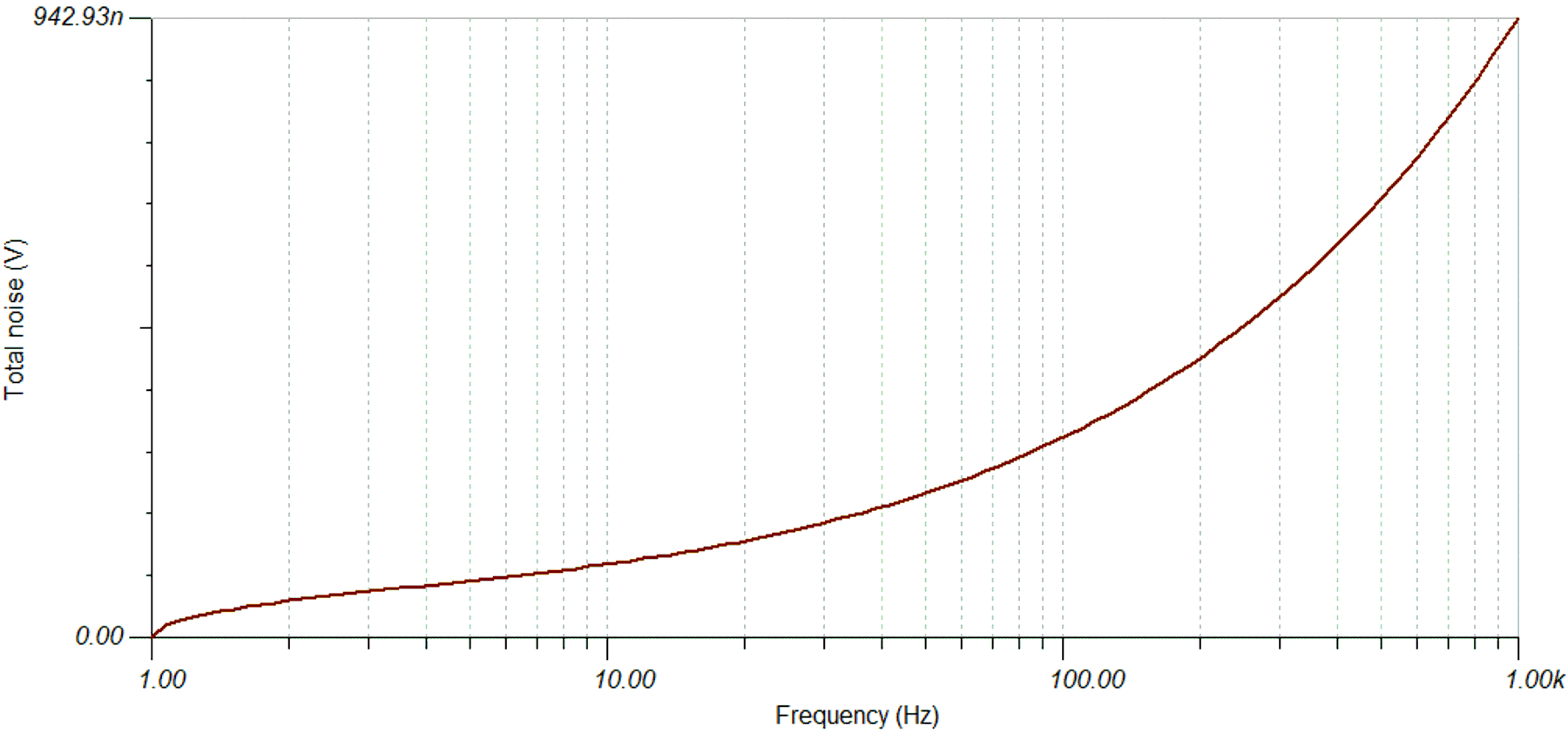
The preconditioning requirements can be targeted with a shelving filter. The easiest approach is a first order circuit. As we are gaining up low frequencies and are dealing with small signals, a low noise OPAMP with auto-zero technology was selected, OPA387. Due to the auto zero feature, the OPAMP removes the 1/f noise and has a flat noise power spectral density of only 8 nV/sqrt(Hz). The circuit further incorporates a matching resistor divider at the non-inverting input to reduce the Ib current based offset error. The shown filter structure is an inverting structure. The output polarity is reversed.
 Figure 3-2 First Order Shelving Filter Circuit
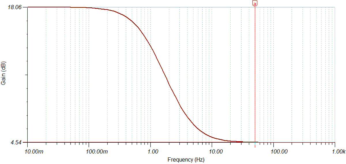
 Figure 3-3 Frequency Response of the First Order
Shelving Filter
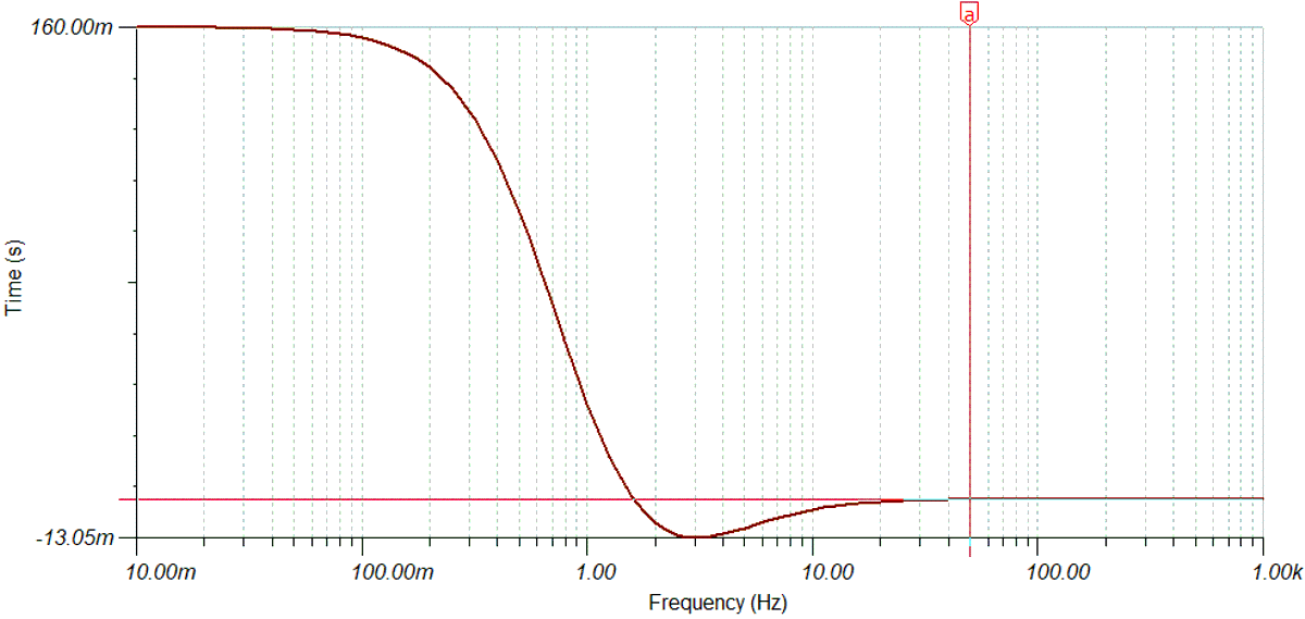
 Figure 3-4 Group Delay of the First Order
Shelving Filter
 Figure 3-5 Total Output Noise of the First Order
Shelving Filter
 Looking at the group delay of such filter, one can see that the response time for detecting a DC failure is about 160 ms. For many applications, 160 ms is not acceptable.