SBOA571 august 2023 OPA2387 , OPA387 , OPA4387
2 Example Considerations
This section provides an example for better understanding. A 16-A, 50-Hz AC current shall be measured including it's harmonics plus a 20-mA DC current within the AC. The sensing approach is shunt-based. The size of the shunt is selected to keep power dissipation low, normally well below 1 W. In the example, the shunt is 1 mOhm.
Power dissipation:
AC peak voltage across the shunt:
DC voltage across the shunt:
Assume an ADC using a 1.2-V VREF with +/-1.2 V full scale swing. For the AC signal, a gain of 54 is required to match full scale. With this gain, the DC voltage results in 1.08 mV. Integrated PGAs inside ADCs normally follow binary gain steps. To avoid clipping one must select a gain of 32; some swing is wasted. At the gain of 32, the AC maximum swing results in a 704-mV peak and the DC maximum is 640 uV. The 640 uV are nearly equal to the LSB size of 585 uV of a 12-bit converter with 1.2V VREF and bipolar +/-VREF swing. Higher resolution converters are needed. Even with a 16-bit converter, the DC resolution is 4-bit only. A 24-bit converter provides more resolution and often contains the PGA. A 50-Hz signal including the 15th harmonic results in 800 Hz analog bandwidth. A typical delta sigma converter using a SINC3 filter has a -3 dB point at . For the 800 Hz desired bandwidth, one must select a 3.2-ksps sample rate. The input referred noise for such delta sigma converters with adjusted gain is in the single digit uVrms range. In relation to the DC signal amplitude of 20 uV, there is only marginal SNR.
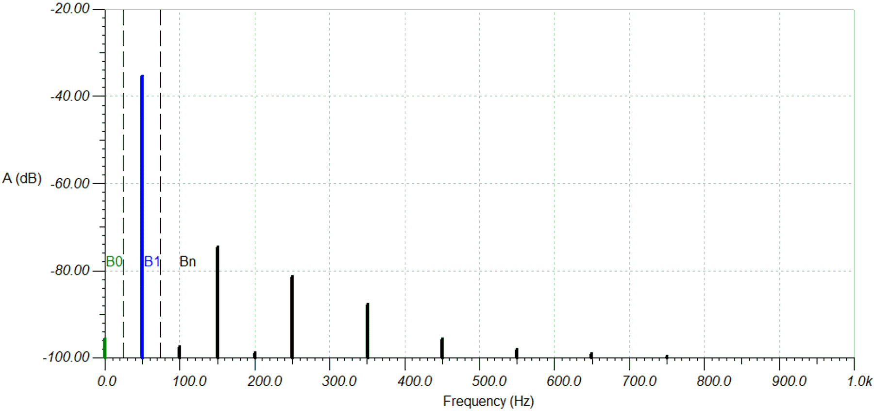
For a better understanding, let's look at the frequency spectrum of the described signal as the result of a coherent FFT calculation. The frequency sample contains 50-Hz wide frequency bins of the fundamental and the harmonic as well as the DC energy.
 Figure 2-1 FFT DC in AC + Harmonics, VREF=1.2V
B0: DC energy bin
B1: AC fundamental bin
Bn: AC harmonic frequency bins