SBOA571 august 2023 OPA2387 , OPA387 , OPA4387
3.4 DC and AC Gain
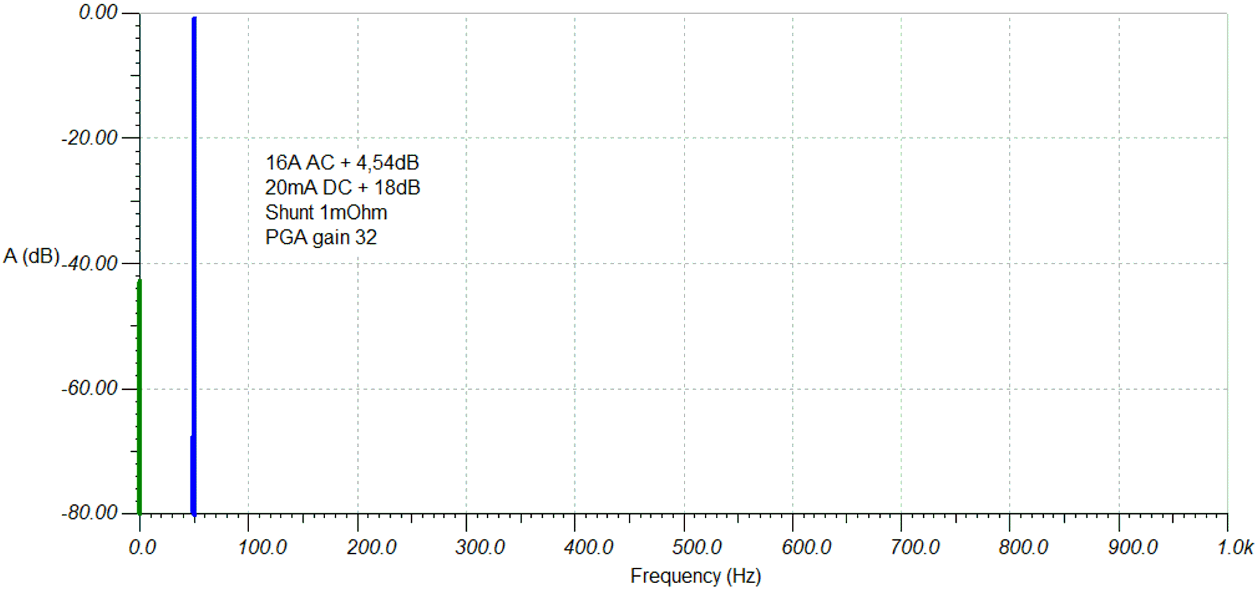
With the additional gain in the DC (+18 dB) and AC (+4.54 dB) bands, the ADC input receives a DC value of 160 uV and an AC value of 37.125 mV. With a PGA gain of 32, the DC value compared to the 1.2-V VREF results in +/-5.12 mV and the AC value reaches full scale +/-1.2 V.
 Figure 3-11 FFT DC in AC With PGA Gain = 32 and Filter Correction, VREF = 1.2 V