SBOA571 august 2023 OPA2387 , OPA387 , OPA4387
5 Influence of Component Tolerances
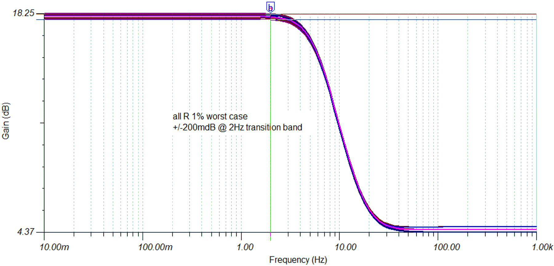
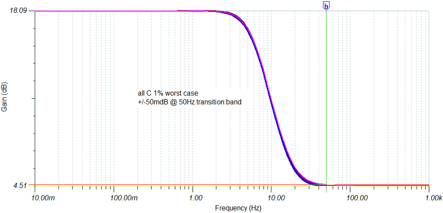
The component tolerances have to be taken into account when using discrete components to realize a filter. Simulations have been performed to understand the error contribution and the sensitivity of the circuit. In a first simulation, all resistor were selected with 1% tolerance and all combination cases plotted. The result is a worst case error contribution in the DC and AC pass band of about +/-0.2 dB. This contribution is equivalent to +/-2.4% gain error. In a second simulation, all capacitors were selected with 1% tolerance. This tolerance varies the frequency corners and the transition band slightly. For our FFT consideration, note how much gain error this adds to the DC or 50-Hz AC bin. The error contribution is in the range of +/-0.05 dB at 50 Hz which is equivalent to +/-0.6% gain error.
Those deviations can be acceptable if a system calibration can be performed. Care must be taken for the drift of the passives and, if needed, more accurate components must be selected.
 Figure 5-1 Frequency Response Worst Case Deviation With All R = 1%
 Figure 5-2 Frequency Response Worst Case Deviation With All C = 1%