SBOU180B november   2016  – july 2023 INA260


  1.   1
  2.   INA260EVM-PDK and Software Tutorial
  3.   Trademarks
  4. 1Overview
    1. 1.1 INA260EVM-PDK Contents
    2. 1.2 INA260EVM-PDK Features
    3. 1.3 Related Documentation from Texas Instruments
  5. 2INA260EVM-PDK Hardware
    1. 2.1 SM-USB-DIG Platform Description
    2. 2.2 INA260EVM PCB Description
      1. 2.2.1 EVM Power Supply
      2. 2.2.2 EVM Analog Inputs
    3. 2.3 EVM Digital Inputs and Outputs
  6. 3INA260EVM-PDK (Rev A) Setup
    1. 3.1 One-Time GUI Software Installation
    2. 3.2 INA260EVM Jumper Settings
    3. 3.3 Connecting the Hardware
    4. 3.4 System Power-Up
  7. 4INA260EVM GUI Software
    1. 4.1 Configuration Tool
      1. 4.1.1 Step 1: Set the I2C Address
      2. 4.1.2 Step 2: Configure Operation
      3. 4.1.3 Step 3: Set Conversion Times
      4. 4.1.4 Step 4: Configure Alert
    2. 4.2 Results Bar
    3. 4.3 Graph Tool
    4. 4.4 Registers Tool
  8. 5INA260EVM Documentation
    1. 5.1 Schematic
    2. 5.2 PCB Layout
    3. 5.3 Bill of Materials
  9. 6Revision History

Step 3: Set Conversion Times

Conversion time determines the sample rate of the INA260 internal ADC and can be programmed depending on the bandwidth of the input signal. The INA260 offers independent control of the conversion time for bus and shunt measurements. Step 3 provides drop-down menus from which suitable values can be selected, as shown in Figure 4-4.
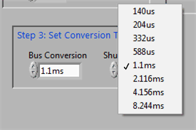
GUID-C1ADFF21-8215-4F35-A953-DC566ACAC018-low.gifFigure 4-4 Configuring Conversion Times