SBOU180B november   2016  – july 2023 INA260


  1.   1
  2.   INA260EVM-PDK and Software Tutorial
  3.   Trademarks
  4. 1Overview
    1. 1.1 INA260EVM-PDK Contents
    2. 1.2 INA260EVM-PDK Features
    3. 1.3 Related Documentation from Texas Instruments
  5. 2INA260EVM-PDK Hardware
    1. 2.1 SM-USB-DIG Platform Description
    2. 2.2 INA260EVM PCB Description
      1. 2.2.1 EVM Power Supply
      2. 2.2.2 EVM Analog Inputs
    3. 2.3 EVM Digital Inputs and Outputs
  6. 3INA260EVM-PDK (Rev A) Setup
    1. 3.1 One-Time GUI Software Installation
    2. 3.2 INA260EVM Jumper Settings
    3. 3.3 Connecting the Hardware
    4. 3.4 System Power-Up
  7. 4INA260EVM GUI Software
    1. 4.1 Configuration Tool
      1. 4.1.1 Step 1: Set the I2C Address
      2. 4.1.2 Step 2: Configure Operation
      3. 4.1.3 Step 3: Set Conversion Times
      4. 4.1.4 Step 4: Configure Alert
    2. 4.2 Results Bar
    3. 4.3 Graph Tool
    4. 4.4 Registers Tool
  8. 5INA260EVM Documentation
    1. 5.1 Schematic
    2. 5.2 PCB Layout
    3. 5.3 Bill of Materials
  9. 6Revision History

INA260EVM-PDK Features

  • USB-powered; no external power supply is required
  • Support for full ±15-A input current range and 36-V common-mode voltage range of the INA260
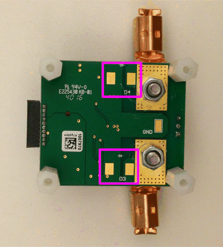
  • EVM includes placeholders for transient voltage suppression (TVS) devices to protect the INA260 inputs from excessively high common-mode voltages
  • Digital host controller included
  • Intuitive GUI software supports all major INA260 functional modes and simplifies device configuration

Note:

To protect against voltage transients that may exceed the absolute maximum ratings, TI highly recommends installing the TVS devices (D3 and D4, as shown in Figure 1-2) with a minimum power rating of 1000 W to clamp the input voltages to less than 36 V.
GUID-400E8C56-9B5F-4860-B4F5-CD510C77D621-low.gif Figure 1-2 Placeholders for TVS Devices